Opel Frontera UBS. Manual - part 2727


  Index      Opel     Opel Frontera UBS - service repair manual 1998-2002 year


Search            


Content   ..  2725  2726  2727  2728   ..


Opel Frontera UBS. Manual - part 2727


8D–108

WIRING SYSTEM

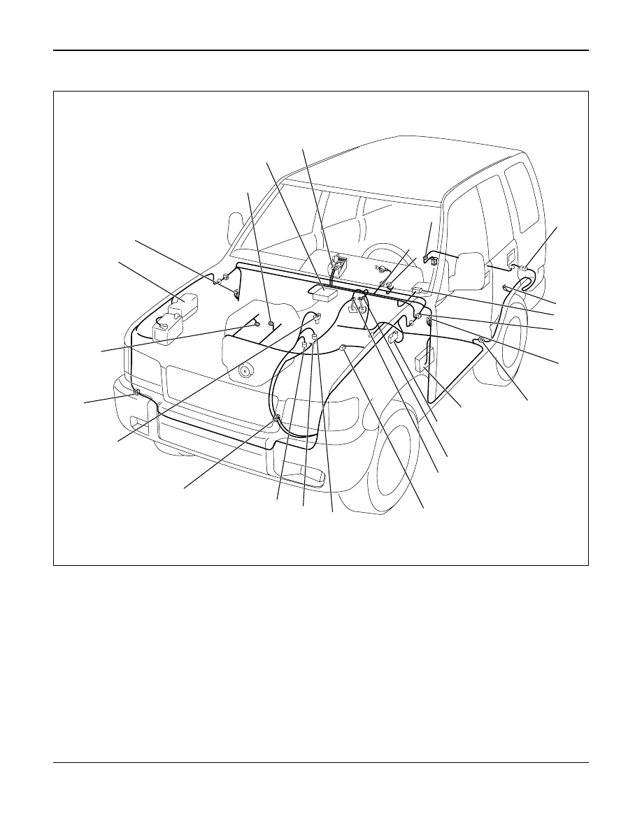
Parts Location (LHD 6V*1) – 2

2

1

26

24

25

23

22

21

20

19

18

17

16

15

14

13

12

11

10

7

9

6

8

5

3

4

D08RW913

Legend

(1) PCM
(2) B-30
(3) B-11
(4) F-4
(5) I-9
(6) H-33
(7) R-4
(8) C-63
(9) H-7, H-8, H-9

(10) B-18, B-19
(11) H-46
(12) Fuse Box
(13) C-16

(14) B-13 or B-14
(15) B-10
(16) H-5
(17) M-7
(18) M-25
(19) M-6
(20) H-10, H-11, H-53
(21) M-15
(22) H-41
(23) E-30
(24) Relay and Fuse Box
(25) B-2
(26) E-28, E-29

WIRING SYSTEM

8D–109

QOS-III (4JG2)

General Description 

The circuit consists of the starter switch, QOS-III
control unit, glow relay, charge relay, fuel cut
solenoid, dropping resistor, thermo sensor, glow
indicator light (meter), glow plug and car speed
sensor.  The engine coolant temperature at the time
of the engine start-up is sensed by the thermo
sensor to change the glow time so that the optimum
starting conditions can always be obtained.
The idling speed just after the engine start-up can
also be placed in the most suitable conditions in
accordance with the coolant temperature by the
operation of the delay timer.

The indicator timer is activated upon the starter
switch turned to the ON position, and the indicator
light comes on for as much time as suitable for the
engine coolant temperature at the time of the
engine start-up.

8D–110

WIRING SYSTEM

Circuit Diagram (RHD)-1

0.5

B

0.85

W/G

0.85

W/G

0.5

B

0.5

B/Y

0.85

B/Y

0.5

L/Y

0.5

L/Y

0.5

P/W

0.85

B/O

0.85

B/O

0.85

B/O

0.3

P/W

0.85

B/Y

0.85

B/Y

3.0

B/Y

C-8 15A

ENGINE

CHARGE

RELA

Y

GLOW

INDICA

T

O

R

LIGHT

(METER)

FUEL

 CUT

SOLENOID

0.85

W/L

QOS III CONTROL

 UNIT

C-66

6

C-66

1

C-66

13

C-66

11

C-66

9

C-39

1

X-17

2

I-9

15

H-41

12

H-9

14

X-17

3

X-17

5

H-3

3

1

X-17

26

I-9

4

X-17

FENDER-RH

ST

AR

TER SW

(IG1)

AC GENERA

T

O

R

(L)

C-10 10A

METER, GAUGE

C-9 15A

FUEL

 CUT

A

19

H-15

3.0

W/G

0.5

W/R

0.5

W/R

C-1 10A

ST

AR

TER

RELA

Y

ST

AR

TER SW

(ST)

4

H-7

0.5

LG/W

0.3

LG/W

VEHICLE SPEED

SENSOR(3)

15

H-5

12

H-7

6

H-26

H-5

7

7

E-37

1

H-7

D08RW982

WIRING SYSTEM

8D–111

Circuit Diagram (RHD)-2

DROPPING

RESIST

OR

GLOW

PLUG

GLOW

RELA

Y

-2

QOS III CONTROL

 UNIT

GLOW

RELA

Y

-1

C-66

12

H-42

16

1

1

C-60

C-59

3.0

R/W

3.0

B/Y

3.0

B/R

0.5

B/G

0.5

B/G

0.85

B/Y

FL-5 50A

GLOW

C-53

1

C-59

2

1

C-54

BA

TT

.(+)

C-55

1

2

C-55

A

C-66

5

H-41

7

3.0

B/R

0.5

B/L

0.5

B/L

0.85

B/Y

0.85

B/Y

3.0

R/W

C-51

1

C-51

C-52

1

2

2

C-52

12

E-41

E-41

QOS THERMO 

SENSOR

(ENGINE)

QOS III CONTROL

 UNIT

C-16

0.5

B

0.5

Y

0.5

Y

0.5

B/Y

0.5

B

7

C-66

10

FENDER

-LH

C-66

8

C-66

4

H-4

8

H-4

12

D08RW980


Content   ..  2725  2726  2727  2728   ..