Content .. 2539 2540 2541 2542 ..
Opel Frontera UBS. Manual - part 2541
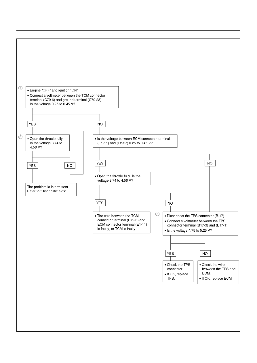
AUTOMATIC TRANSMISSION (AW30-40LE)
7A–27
DTC P0120 (FLASHING CODE 21) ANALOG THROTTLE SIGNAL FAILURE (VTH)
DTCP0120
|
|
|
Content .. 2539 2540 2541 2542 ..
AUTOMATIC TRANSMISSION (AW30-40LE) 7A–27 DTC P0120 (FLASHING CODE 21) ANALOG THROTTLE SIGNAL FAILURE (VTH) DTCP0120 |