Opel Frontera UBS. Manual - part 2525


  Index      Opel     Opel Frontera UBS - service repair manual 1998-2002 year


Search            


Content   ..  2523  2524  2525  2526   ..


Opel Frontera UBS. Manual - part 2525


7A–58

AUTOMATIC TRANSMISSION (4L30–E)

D

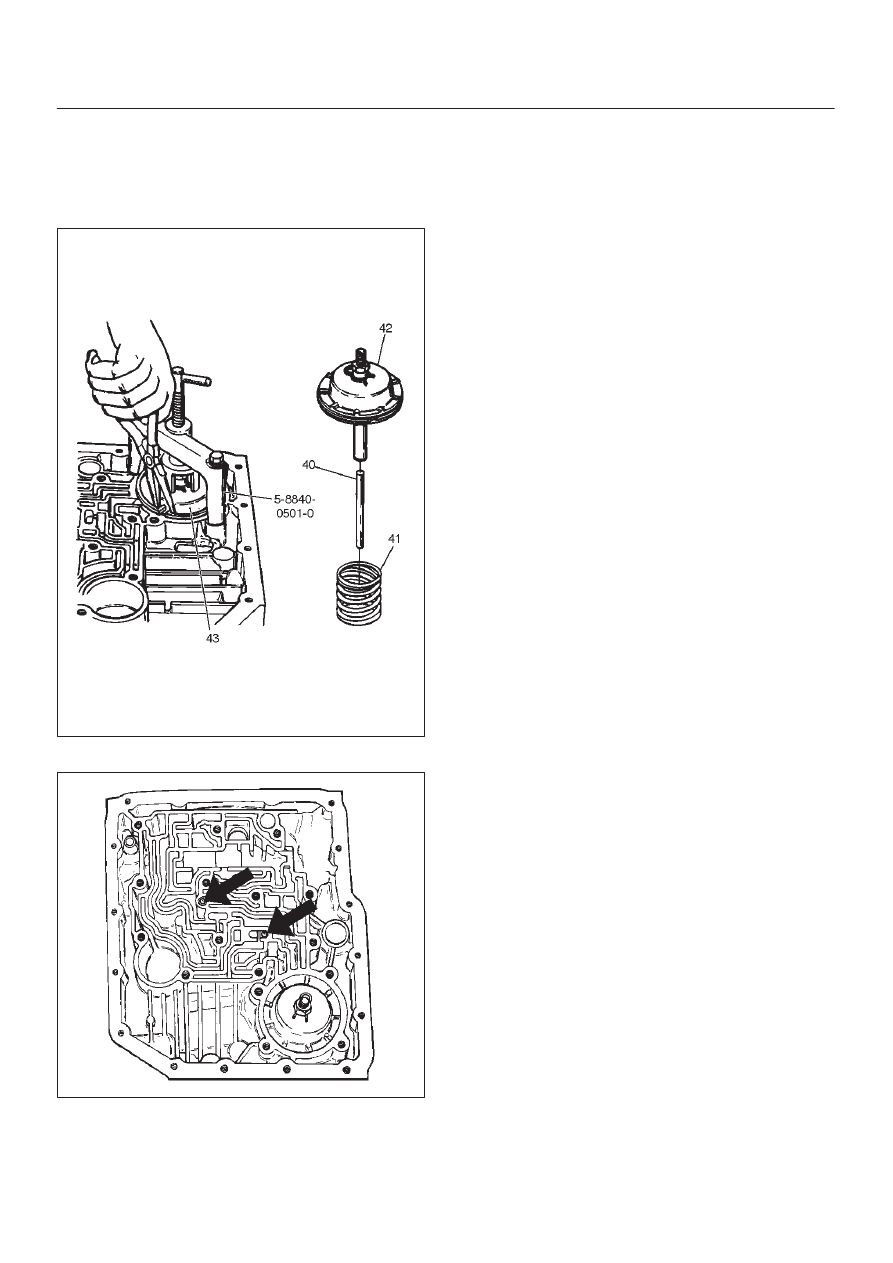
Adjust the brake band by tightening the servo
adjusting screw to 4.5 N·m torque.  Be certain the
lock nut is loose, then back–off the screw five turns
exactly. Hold piston sleeve with wrench and tighten
lock nut to 18.5 N·m torque. Be certain the adjusting
screw does not turn. 

242RW008

46. Install two check balls (44).

244RW002

47. Inspect main case electrical connector and seal,

replace if necessary.

D

Install electrical 7 way connector/main case and
wiring harness.

48. Install two 5–8840–0022–0 (J–25025–B) guide pins

into main case.

D

Install main case valve body complete assembly
(45) and manual valve link.

NOTE: Valve must be extended as the short end of
manual valve link is connected to the range selector lever.
Long end of link goes into valve.

D

Install seven 13 mm screws.

Torque: 20 N

m (2.0 kg·m/15 Ib ft)

D

Remove two guide pins.

49. Install servo cover gasket, cover (46) and four 13 mm

screws.

Torque: 25 N

m (2.6 kg·m/18 Ib ft)

50. Connect wiring harness (47) to band control, shift

solenoids, and main case 7 way connector.

51. Install manual detent roller and spring assembly (48)

with clip.

D

Install two 13 mm screws.

Torque: 20 N

m (2.0 kg·m/15 Ib ft)

52. Install oil filter (49), and three 13 mm screws.

Torque: 20 N

m (2.0 kg·m/15 Ib ft)

53. Install oil pan gasket, magnet, main oil pan (50), and

sixteen 10 mm screws.

Torque: 11 N

m (1.1 kg·m/96 Ib in)

54. Inspect adapter case electrical connector and seal.

Replace if necessary.

D

Install electrical five pin connector and harness
assembly (52) in bottom of adapter case.

55. Install gasket, transfer plate, and gasket.

D

Install adapter case valve body (51) and seven 13
mm screws.

Torque: 20 N

m (2.0 kg·m/15 Ib ft)

56. Connect wiring harness harness assembly (52) to

converter clutch PWM solenoid, force motor, and 4
way connector.

57. Install oil pan gasket, adapter case oil pan (53), and

twelve 10 mm screws.

Torque: 11 N

m (1.1 kg·m/96 Ib in)

D

Rotate transmission, with bottom pan facing down.

58. Install mode switch (54), two 10 mm screws, selector

lever nut, and cover.

10 mm screw

Torque: 13 N

m (1.3 kg·m/113 Ib in)

Nut

Torque: 23 N

m (2.3 kg·m/17 Ib ft)

D

Adjust using setting tool, refer to Mode Switch in
this section.

7A–59

AUTOMATIC TRANSMISSION (4L30–E)

59. Install O–ring (55) on turbine shaft.
60. Install torque converter (56).

The converter assembly must be replaced under any
of the following conditions:

a. Evidence of damage to the pump assembly.
b. Metal particles are found after flushing the cooler

lines.

c. External leaks in hub weld area.
d. Converter pilot broken, damaged, or poor fit into

crankshaft.

e. Converter hub scored or damaged.
f. Internal failure in stator.
g. Contamination from engine coolant.
h. Excess end play.

D

Rotate transmission, bell housing up.  Spin
converter to insure proper fit.

61. Fill transmission through the overfill screw hole of oil

pan, using ATF DEXRON

–III. Refer to Changing

Transmission Fluid in this section.

240RY002

7A–60

AUTOMATIC TRANSMISSION (4L30–E)

Converter Housing And Oil Pump Assembly

Disassembled View

241RY001

Legend

(1) Converter Housing
(2) Outer Seal Ring
(3) Gasket

(4) Wear Plate
(5) Oil Pump Assembly
(6) Oil Seal Ring

Disassembly

1. Remove oil pump assembly from converter housing. 
2. Remove outer seal ring. 
3. Remove gasket. 
4. Remove wear plate. 
5. Remove oil seal ring.

Inspection And Repair

Visual Check:

If any damage, deformation, or local wear is found in a
converter housing, outer seal ring, wear plate, or oil seal
ring, replace it.

Reassembly

1. Install wear plate onto oil pump assembly.
2. Install converter housing onto complete oil pump

assembly. Align with two short 5–8840–2268–0
(J–38588) guide pins on outer bolt holes.

D

Loosely install five 13mm bolts.

D

Center converter housing using 5–8840–2272–0
(J–38557) centering tool.

D

Tighten five inner 13mm bolts in an alternating
pattern.

Torque: 20 N

m (2.0 kg·m/15 Ib ft)

241RW020

3. Install oil seal ring (3 screws).

Torque: 3 N

m (0.3 kg·m/26 Ib in)

4. Install gasket. 
5. Install outer seal ring. 

7A–61

AUTOMATIC TRANSMISSION (4L30–E)

Oil Pump

Disassembled View

241RY002

Legend

(1) Oil Pump Drive Gear
(2) Oil Pump Driven Gear
(3) Pin
(4) Plug
(5) Seal Ring
(6) Torque Converter Clutch Control Valve
(7) Converter Clutch Control Valve Spring
(8) Pin
(9) Converter Clutch Regulator Sleeve

(10)

Converter Clutch Regulator Spring

(11)

Converter Clutch Regulator Valve

(12)

Isolator Spring

(13)

Isolator Valve

(14)

Pin

(15)

Enable Valve Spring Guide

(16)

Enable Valve Spring

(17)

Enable Valve

(18)

Snap Ring

(19)

Spring Seat

(20)

Throttle Signal Accumulator Spring

(21)

Throttle Signal Accumulator Piston

(22)

Sleeve Pin

(23)

Boost Valve Sleeve

(24)

Boost Valve

(25)

Spring Seat

(26)

Pressure Regulator Valve Spring

(27)

Spring Seat

(28)

Pressure Regulator Valve

(29)

Oil Pump Assembly

Disassembly

1. Remove oil pump drive gear (1) and driven gear (2).
2. Remove pin (3) from oil pump assembly (29).
3. Remove plug (4) and seal ring (5), torque converter

clutch control valve (6) and spring (7).

4. Remove pin (8) from oil pump assembly (29).

5. Remove torque converter regulator sleeve (9),

converter clutch regulator spring (10), converter
clutch regulator valve (11), isolator spring (12) and
isolator valve (13).

6. Remove pin (14) from oil pump assembly (29).
7. Remove enable valve spring (16), spring guide (15)

and enable valve (17).

8. Remove snap ring (18) from oil pump assembly (29).


Content   ..  2523  2524  2525  2526   ..