Opel Frontera UBS. Manual - part 252


  Index      Opel     Opel Frontera UBS - service repair manual 1998-2002 year


Search            


Content   ..  250  251  252  253   ..


Opel Frontera UBS. Manual - part 252


6A–75

ENGINE MECHANICAL

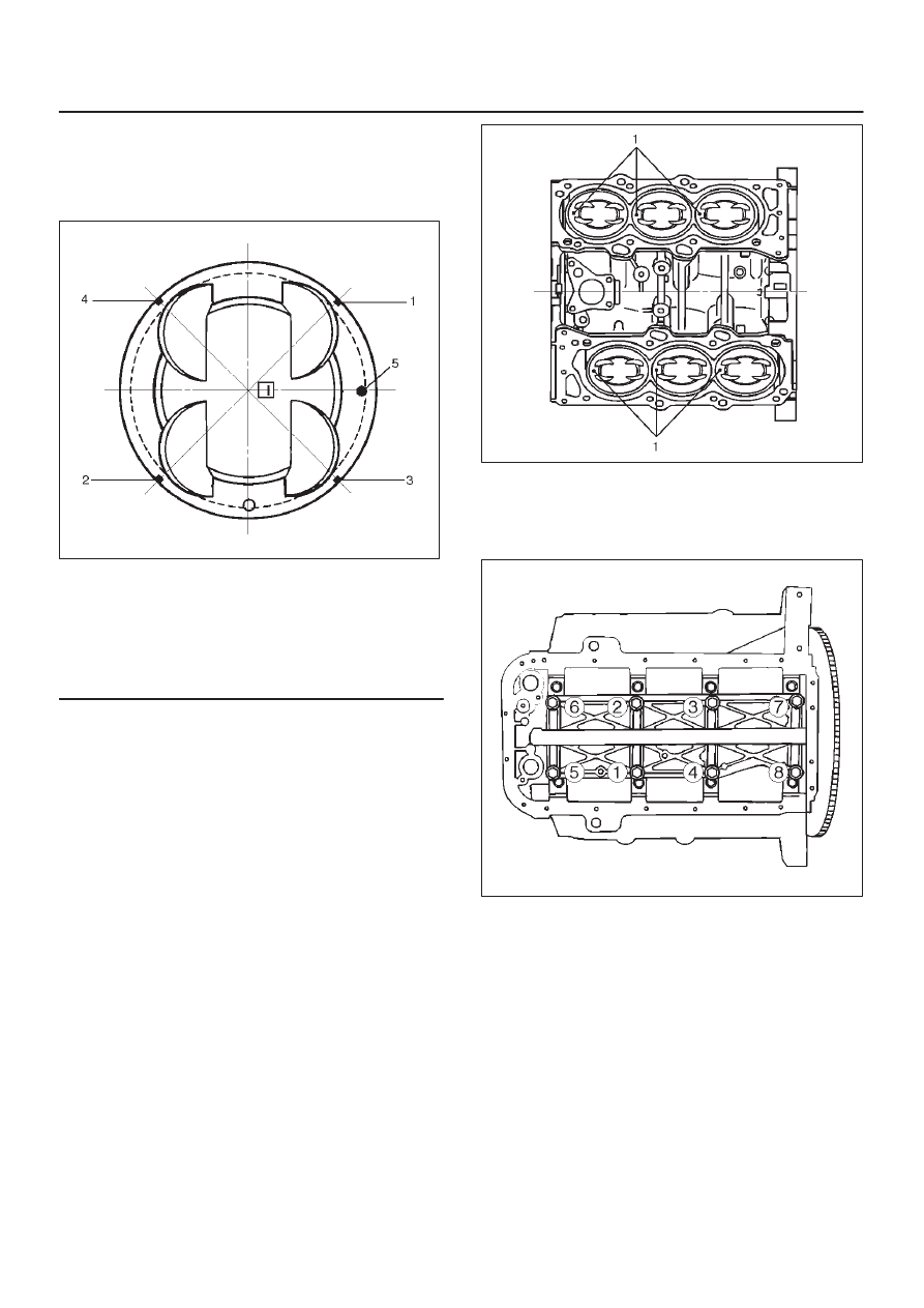
4. Piston and connecting rod assembly (8)

D

Apply engine oil to the cylinder bores, the
connecting rod bearings and the crankshaft pins.
Check to see that the piston ring end gaps are
correctly positioned.

015RS019

Legend

(1) No.1 Compression Ring
(2) No.2 Compression Ring
(3) Oil Ring Side Rail Upper
(4) Oil Ring Side Rail Lower
(5) Piston Front Mark

D

Insert the piston/connecting rod assemblies into
each cylinder with the piston ring compressor. The
front marks must be facing the front of the engine.

D

Match the numbered caps with the numbers on the
connecting rods. Align the punched marks on the
connecting rods and caps.

D

Apply engine oil to the threads and seating faces of
the nuts.

D

Tighten the nuts.

Torque: 54 N·m (5.5 Kg·m/40 lb ft)

After tightening the cap nuts, check to see that the
crankshaft rotates smoothly.

NOTE: Do not apply engine oil to the bearing back faces.

015RS020

5. Install oil gallery (7) and tighten the bolts in 2 steps, in

the order shown.

1st step: 29 N·m (3.0 Kg·m/22 lb ft)
2nd step: 55

°

 65

°

051RS009

6. Cylinder block side bolts (6)

D

Tighten all the bolts to the specified torque in the
order shown.

NOTE: Do not apply engine oil to the crank case side
bolts.

Torque: 39 N·m (4.0 Kg·m/29 lb ft)

6A–76

ENGINE MECHANICAL

012RS001

7. Install oil pump assembly (5), refer to “Oil pump” in

this manual.

8. Install oil strainer and O-ring (4).
9. Install oil pipe and O-ring (3) and tighten the bolts.

Torque: 25 N·m (2.5 Kg·m/18 lb ft)

10. Install crankcase with oil pan (2).

1. Completely remove all residual sealant, lubricant

and moisture from the sealing surfaces. The
surfaces must be perfectly dry.

2. Apply a correct width bead of sealant (TB—

1207C or its equivalent) to the contact surfaces of
the oil pan. There must be no gaps in the bead.

3. The crankcase assembly must be installed within

5 minutes after sealant application to prevent
premature hardening of the sealant.

4. Tighten the bolts and nuts to the specified torque.

Torque : 10 N·m (1.0 Kg·m/89 lb in)

013RW010

Legend

(1) Portion Between Bolt Holes
(2) Bolt Hole Portion

11. Install cylinder head assembly, refer to “Cylinder

head” in this manual.

6A–77

ENGINE MECHANICAL

Piston and Connecting Rod

Piston, Connecting Rod and Associate Parts

015RW019

Legend

(1) Cylinder Head Assembly
(2) Cylinder Head Gasket
(3) Crankcase with Oil Pan
(4) Oil Pipe and O-Ring
(5) Oil Strainer and O-Ring
(6) Oil Gallery

(7) Piston and Connecting Rod Assembly
(8) Piston Ring
(9) Piston Pin

(10) Piston

(11) Connecting Rod

(12) Connecting Rod Cap

Disassembly

1. Remove cylinder head assembly (1). Refer to

“Cylinder Head Removal” in this manual.

2. Remove cylinder head gasket (2).
3. Remove crankcase with oil pan (3). Refer to“Oil Pan

and Crankcase” in this manual.

4. Remove oil pipe and O-ring (4).

5. Remove oil strainer and O-ring (5).
6. Remove oil gallery (6).
7. Remove connecting rod cap with connecting rod

lower bearing (12).

8. Remove piston and connecting rod assembly (7).

NOTE: Before removing piston and connecting rod
assembly, measure thrust clearance.

6A–78

ENGINE MECHANICAL

015RS031

D

Remove any ridge or carbon build up from the top
end of the cylinder.

9. Remove the piston rings (8) with a piston ring

expander. Arrange the removed piston rings in the
cylinder number order.

015RS022

10. Remove the piston pin (9) using 5–8840–0551–0

piston pin service set and piston support with a press.

NOTE: Keep the parts removed from each cylinder
separate.  All parts must be reinstalled in their original
positions.  Heating the connecting rod will permit easy
removal of the piston pin.

015RX001

Legend

(1) Press Ram
(2) Piston
(3) Connecting Rod
(4) Piston Pin

11. Piston (10)

12. Connecting rod (11)

Inspection and Repair

Pistons (10)

Carefully clean away all the carbon adhering to the piston
head and the piston ring grooves.

NOTE: Never use a wire brush to clean the pistons.
Damage will result. Visually check each piston for
cracking, scoring, and other signs of excessive wear. If
any of the above conditions are found, the piston must be
replaced.

Piston Diameter

1. Measure the piston outside diameter with micrometer

at the piston grading position and a right angle to the
piston pin.
Piston grading position (from piston head)

Piston grading position : 43.0 mm (1.6929 in)


Content   ..  250  251  252  253   ..