Opel Frontera UBS. Manual - part 248


  Index      Opel     Opel Frontera UBS - service repair manual 1998-2002 year


Search            


Content   ..  246  247  248  249   ..


Opel Frontera UBS. Manual - part 248


6A–59

ENGINE MECHANICAL

Limit: 39.47 mm (1.5539 in)
Exhaust
Standard: 39.30 mm (1.5472 in)
Limit: 39.45 mm (1.5531 in)

014RW047

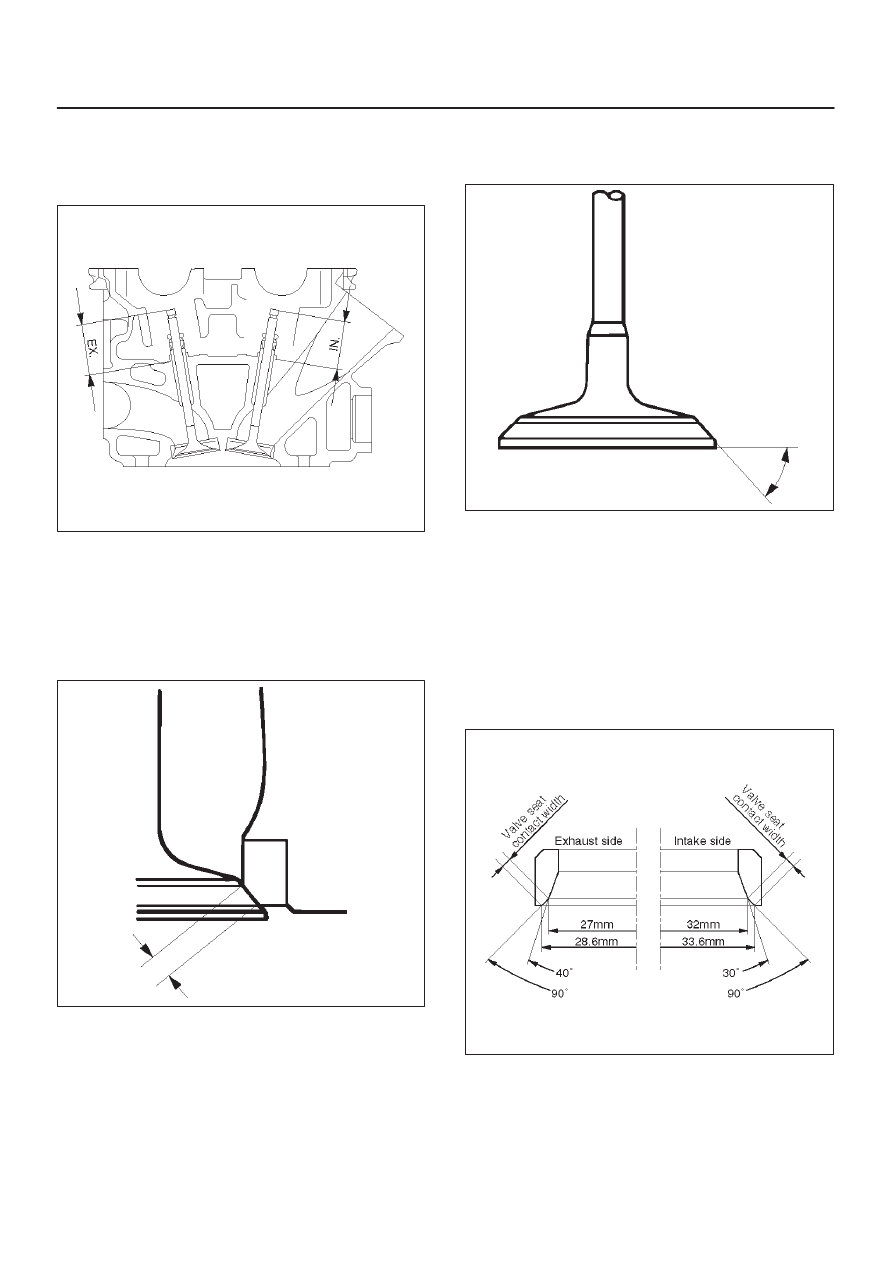
2. Measure the valve seat contact width. Make the

necessary corrections if the seat contact surface is
damaged or rough or if the contact width wear
exceeds the limit.

Valve seat contact width
Standard: 1.1 mm (0.0433 in)
Limit: 1.7 mm (0.0669 in)

014RS011

Contact Surface Angle on Valve Seat on
Valve

1. Measure contact surface angle on valve seat.

2. If the measured value exceeds the limit, replace

valve, valve guide and valve seat as a set.

Valve contact surface angle: 45

°

014RS012

Valve Seat Insert Correction

1. Remove the carbon from the valve seat insert

surface.

2. Use a valve cutter to minimize scratches and other

rough areas. This will bring the contact width back to
the standard value. Remove only the scratches and
rough areas. Do not cut away too much. Take care not
to cut away unblemished areas of the valve seat
surface.

Valve seat angle degree: 90

°

014RW059

3. Apply abrasive compound to the valve seat insert

surface.

4. Insert the valve into the valve guide.
5. Turn the valve while lapping it to fit the valve seat

insert.

6A–60

ENGINE MECHANICAL

6. Check that the valve contact width is correct.
7. Check that the valve seat insert surface is in contact

with the entire circumference of the valve.

014RS014

Valve Seat Insert Replacement

1. Arc weld the rod at several points. Be careful not to

damage the aluminum section.

2. Allow the rod to cool for a few minutes. This will cause

the valve seat to shrink.

3. Strike the rod and pull it out.

014RS015

4. Carefully clean the valve seat press–fit section on the

cylinder head side.

5. Heat the press–fit section with steam or some other

means to cause expansion. Cool the valve seat with
dry ice or some other means.

6. Insert the press–fit section into the valve seat

horizontally.

Standard fitting interference: 0.14 mm–0.09 mm
(0.0055 in–0.0035 in)

7. After insertion, use a seat grinder to grind finish the

seating face. Carefully note the seating angle, the
contact width, and the depression.

8. Lap the valve and the seat.

Reassembly

1. Install valve guide (1) to cylinder head. Apply engine

oil to the outside of the valve guide. Using valve guide
replacer 5–8840–2442–0, drive in a new valve guide
from the camshaft side.

2. Install oil controller (3) and spring lower seat (2).

Using oil controller replacer 5–8840–0623–0, drive in
a new oil controller.

014RW058

3. Install valve to valve guide. Before install valve guide

apply engine oil to the outside of the valve stem.

4. Install valve spring to cylinder head. Attach the valve

spring to the lower spring seat. The painted area of
the valve spring should be facing downward.

014RS020

6A–61

ENGINE MECHANICAL

5. Install lower valve spring seat, valve spring and upper

valve spring seat then put split collars on the upper
spring seat, using the 5–8840–2446–0 valve spring
compressor and 5–8840–2547–0 valve spring
compressor adapter to install the split collars.

014RW042

6. Install tappet with shim.
7. Install camshaft assembly.

D

Refer to installation procedure for Camshaft in this
manual.

Valve Clearance Adjustments

NOTE: To adjust valve clearance, apply engine oil to the
cam as well as to the adjusting shim (2) with the cylinder
head built on the cylinder block, give a few turns to the
camshaft by means of timing pulley tightening bolt, and
measure valve clearance when the nose of cam is just
opposite to maximum cam lift (1) as shown in illistration
below.

014RW081

Legend

(1) Cam
(2) Shim
(3) Tappet

Valve Clearance Standard Value (cold)

Intake: 0.23 mm–0.33 mm

(0.0091 in–0.0130 in)

Exhaust: 0.25 mm–0.35 mm

(0.0098 in–0.0138 in)

Selection of Adjusting Shim

Shim to be selected = (Thickness of removed shim) +
(Valve clearance measurement – Standard valve)
Based on the above formula, the best suited shim should
be selected from 41 sorts of shim (differently thick at
0.02mm (0.0008 in) intervals from 2.40mm (0.0945 in)
through 3.2mm (0.1260 in) thick). Install the shim and
check valve clearance.

6A–62

ENGINE MECHANICAL

Replacement of Shim

Let the cam push down the edge of tappet by using
5–8840–2444–0 valve clearance adjusting tool and push
out the shim with a flat blade screw driver as shown in
illustrations below.

014RW082

014RW083

014RW084


Content   ..  246  247  248  249   ..