Opel Frontera UBS. Manual - part 245


  Index      Opel     Opel Frontera UBS - service repair manual 1998-2002 year


Search            


Content   ..  243  244  245  246   ..


Opel Frontera UBS. Manual - part 245


6A–47

ENGINE MECHANICAL

Rear Oil Seal

Removal

1. Remove transmission assembly.

D

Refer to removal procedure for Transmission
section in this manual.

2. Remove flywheel.
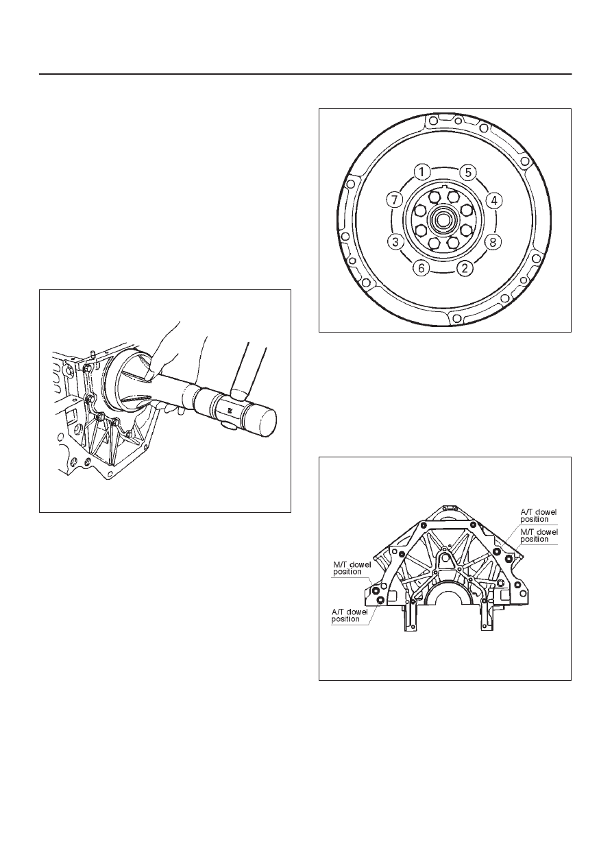
3. Remove rear oil seal using a seal remover.

NOTE: Take care not to damage the crankshaft or oil seal
retainer when removing oil seal.

Installation

1. Apply engine oil to oil seal lip and install oil seal using

5–8840–2286–0.

015RS017

2. Install flywheel.

D

Clean tapped holes in the crankshaft.

D

Remove oil on the crankshaft and flywheel
mounting surface.

D

Tighten fixing bolts to the specified torque.

NOTE: Do not reuse the bolts and do not apply oil or
thread lock to the bolts.

Torque : 54 N·m (5.5 Kg·m/40 lb ft)

015RS018

3. Install transmission.

D

See Transmission section in this manual.

CAUTION: When  assembling the engine and
transmission, confirm that dowels have been
mounted in the specified positions at the engine
side. Take care that dowel positions are different
between the manual transmission and the automatic
transmission.
Otherwise, the transmission may be damaged.

012RS009

6A–48

ENGINE MECHANICAL

Engine Assembly

Removal

035RW027

1. Disconnect battery ground and positive cable.
2. Remove battery.
3. Make alignment mark on the engine hood and hinges

before removal in order to return the hood to original
position exactly.

4. Remove engine hood.
5. Drain radiator coolant.
6. Disconnect accelerator cable and automatic cruise

control cable from throttle valve on common
chamber.

7. Disconnect air duct with air cleaner cover.
8. Remove air cleaner assembly.
9. Disconnect canister vacuum hose.

10. Disconnect vacuum booster hose.

11. Disconnect three engine harness connectors.

12. Disconnect harness connector to transmission (left

front side of engine compartment), disconnect shift
on the fly harness connector from front side of front
axle and remove transmission harness bracket from
engine left side.

13. Disconnect ground cable between engine and frame.
14. Disconnect bonding cable connector on the back of

right dash panel.

15. Disconnect bonding cable terminal on the left bank.
16. Disconnect starter harness connector from starter.
17. Disconnect generator harness connector from

generator.

18. Disconnect coolant reserve tank hose from radiator.
19. Remove radiator upper and lower hoses.
20. Remove upper fan shroud.
21. Remove cooling fan assembly four fixing nuts, then

the cooling fan assembly.

22. Move drive belt tensioner to loose side using wrench

then remove drive belt.

23. Remove power steering pump fixing bolts, then

power steering pump. Place the power steering pump
along with piping on the body side.

24. Remove air conditioning compressor fixing bolts from

bracket and place the compressor along with piping
on the body side.

25. Remove O

2

 sensor harness connectors from exhaust

front pipe.

26. Remove three exhaust pipe fixing nuts from each

bank.

27. Remove two exhaust pipe fixing nuts from each

exhaust pipe, then move exhaust pipe to rear side of
vehicle.

28. Remove flywheel dust covers.
29. Disconnect two heater hoses from engine.
30. Disconnect fuel hoses from right side of transmission.

CAUTION: Plug fuel pipes on engine side and fuel
hoses from fuel tank.

31. Remove transmission assembly. Refer to

Transmission section in this manual.

32. Support the engine by engine hoist.
33. Remove two left side engine mount fixing bolts from

engine mount on chassis side.

34. Remove two right side engine mount fixing bolts from

engine mount on chassis side.

35. Remove engine assembly.

Installation

CAUTION: When  assembling the engine and
transmission, confirm that dowels have been
mounted in the specified positions at the engine
side. Take care that dowel positions are different
between the manual transmission and the automatic
transmission.

6A–49

ENGINE MECHANICAL

If the engine is assembled in the condition that the
dowels have not been mounted in the specified posi-
tions, the transmission may be damaged the trans-
mission.

012RS009

1. Install engine assembly. Tighten engine mount fixing

bolts to frame to the specified torque.

Torque: 41 N·m (4.2 Kg·m/30 lb ft)

2. Reconnect fuel hose to fuel pipe on engine.
3. Install transmission assembly. Refer to Transmission

section in this manual.

4. Reconnect two heater hoses to engine.
5. Install flywheel dust covers.
6. Install exhaust pipe and temporally tighten two (each

bank) rear exhaust flange nuts then tighten three stud
nuts (each bank) between exhaust manifold and
exhaust pipe, finally tighten rear side nuts to the
specified torque.

Torque:
Nuts: 43 N·m (4.4 Kg·m/32 lb ft)
Stud nuts: 67 N·m (6.8 Kg·m/49 lb ft)

150RW061

Legend

(1) Exhaust Front Pipe RH
(2) O

2

 Sensor (for IGM)

150RW062

Legend

(1) Exhaust Front Pipe LH

7. Reconnect O

2

 sensor connector.

8. Install cooling fan assembly and tighten bolts/nuts to

the specified torque.

Torque : 22 N·m (2.2 Kg·m/16 lb ft) for fan pulley
and fan bracket.

Torque : 10 N·m (1.0 Kg·m/88.5 lb in) for fan and
clutch assembly.

6A–50

ENGINE MECHANICAL

9. Install air conditioner compressor to engine and

tighten to the specified torque.

Torque :
M8 bolts : 22 N·m (2.2 Kg·m/16 lb ft)
M10 bolts : 43 N·m (4.4 Kg·m/32 lb ft)

10. Install power steering pump, tighten fixing bolt to the

specified torque.

Torque :
M8 bolts : 22N·m (2.2 Kg·m/16 lb ft)
M10 bolts : 46 N·m (4.7 Kg·m/34 lb ft)

11. Move drive belt tensioner to loose side using wrench,

then install drive belt to normal position.

850RW001

Legend

(1) Crankshaft Pulley
(2) Cooling Fan Pulley
(3) Tensioner
(4) Generator
(5) Air Conditioner Compressor
(6) Power Steering Oil Pump
(7) Drive Belt

12. Install upper fan shroud.
13. Reconnect radiator upper and lower hoses.
14. Reconnect coolant reserve tank hose to radiator.
15. Reconnect generator harness connector.
16. Reconnect starter harness connector.
17. Reconnect bonding cable terminal on left bank
18. Reconnect bonding cable terminal on the back of right

dash panel.

19. Reconnect ground cable between engine and

chassis.

20. Reconnect harness connector to transmission and

install transmission harness bracket on engine left
side.

21. Reconnect three engine harness connectors.
22. Reconnect vacuum booster hose.
23. Reconnect canister vacuum hose.
24. Install air cleaner assembly.
25. Reconnect air duct.
26. Reconnect accelerator cable and automatic cruise

control cable to throttle valve on common chamber.

035RW007

Legend

(1) Throttle Valve Assembly
(2) Throttle Lever
(3) Idle Air Control Valve
(4) Throttle Position Sensor

27. Install engine hood to the original position.

D

Refer to installation procedure for Body section in
this manual.

Accelerator pedal cable adjustment

1. Loosen adjusting nut and lock nut.

2. Pull outer cable while fully closing the throttle

valve.

3. Tighten adjusting nut and lock nut temporarily.

4. Loosen adjusting nut by three turns and tighten

lock nut.
Then, manually operating the throttle valve, make
sure that the valve lever returns up to the stopper
screw.


Content   ..  243  244  245  246   ..