Content .. 2425 2426 2427 2428 ..
Opel Frontera UBS. Manual - part 2427
6E–22
4JX1–TC ENGINE DRIVEABILITY AND EMISSIONS
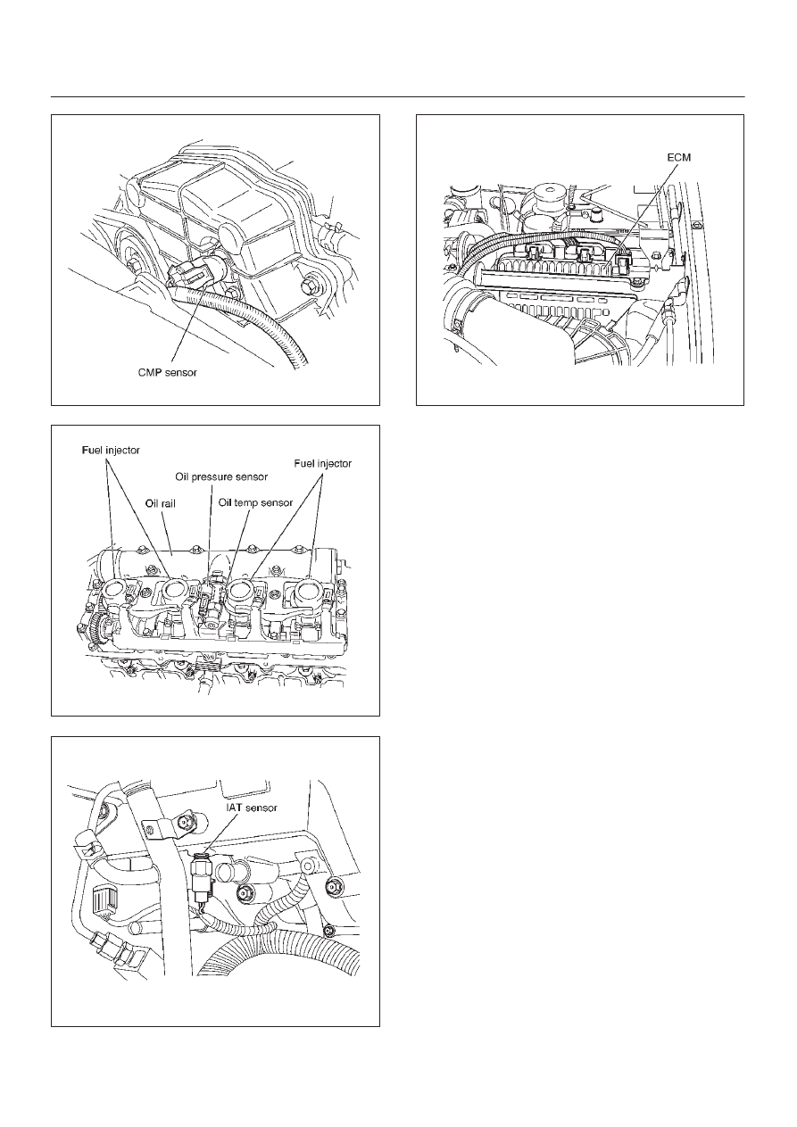
035RW121
035RW122
035RW116
035RW107
|
|
|
Content .. 2425 2426 2427 2428 ..
6E–22 4JX1–TC ENGINE DRIVEABILITY AND EMISSIONS 035RW121 035RW122 035RW116 035RW107 |