Opel Frontera UBS. Manual - part 2414


  Index      Opel     Opel Frontera UBS - service repair manual 1998-2002 year


Search            


Content   ..  2412  2413  2414  2415   ..


Opel Frontera UBS. Manual - part 2414


6C – 18 ENGINE FUEL

4. Remove lock bolt of idle gear A.
5. Install timing gear case cover.

Refer to “Timing gear” in this manual.

6. Install front plate.

Torque: 20 N·m (2.0 kg·m/14 lb ft)

7. Install timing pulley of high pressure oil pump.

Torque: 10 N·m (1.0 kg·m/87 lb in)

8. Install timing belt and tighten timing belt tensioner

assembly.
Refer to “Cylinder head” in this manual.
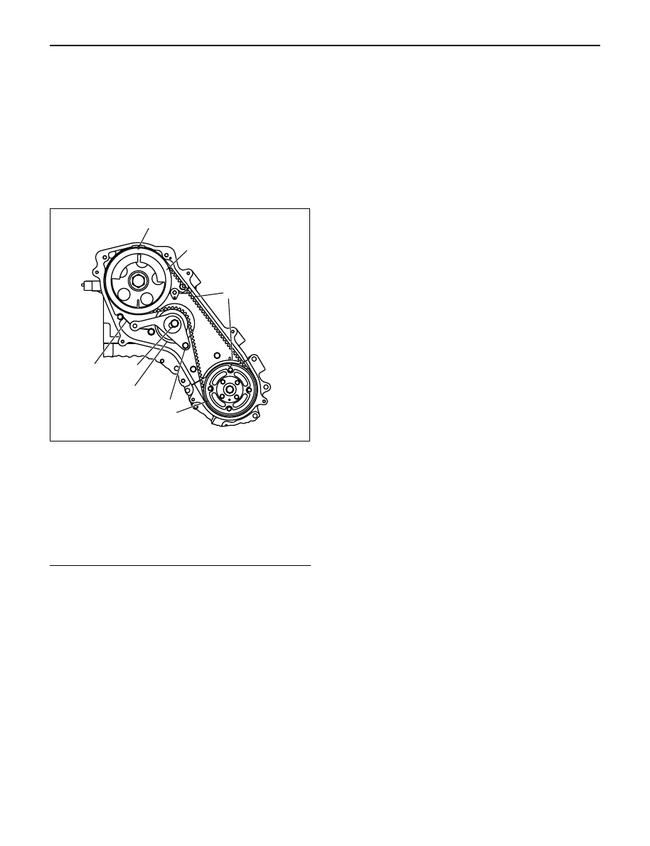
Legend

(1) Align Mark
(2) Camshaft Pulley
(3) Timing Belt
(4) High Pressure Oil Pump Pulley
(5) Tensioner Bolt B
(6) Tensioner Assembly
(7) Tensioner Bolt A
(8) Tensioner Spring

9. Install CMP sensor bracket.

Torque: 20 N·m (2.0 kg·m/14 lb ft)
10. Connect CMP sensor cable.
11. Install timing belt cover.

Torque: 9 N·m (0.9 kg·m/78 lb in)
12. Fill with about 300 cc of engine oil from the high

pressure oil pipe installation port of the oil rail using
an oil filler.
If assembled without filling the oil rail with oil, the
time for engine starting will be longer.

13. Immediately install high pressure oil pipe and

tighten to specified torque.

NOTE:

1) Use new O-ring.
2) Clean O-ring groove and fitting surface of parts.
3) Apply engine oil to O-ring.

Torque: 78 N·m (8.0 kg·m/58 lb ft)

14. Install the crankshaft damper pulley with specified

torque.

Torque: 216 N·m (22 kg·m/159 lb ft)
15. Install the intercooler assembly.

Refer to “Intercooler” in this manual.

16. Install air cleaner cover and air duct.

1

2

3

8

6

7

4

5

F06R200006

ENGINE FUEL 6C – 19

HIGH PRESSURE OIL PIPE INSTALLATION

1. Install upper bracket to two way valve, tighten them

temporarily.

2. Install pipe A to two way valve, tighten pipe A

temporarily with union nut D.

3. Install two way valve assembly to cylinder block,

tighgten with union nut C temporarily.

4. Install pipe B to two way valve, tighten union nut E

and union nut F temporarily.

5. Tighten upper bracket to specified torque.

Torque : 20 N·m (2.0 kg·m/14 lb ft)

6. Tighten union nut in the following order, union nut

C, D, F, and E to the specified torque.

Torque : 78 N·m (8.0 kg·m/58 lb ft)

7. Tighten lower bracket to the specified torque.

Torque : 20 N·m (2.0 kg·m/14 lb ft)

NOTE: Wash inside pipe, inside union nut and O-ring
seal surface to remove engine oil and foreign materials.

6

5

7

9

8

11

4

1

2

3

10

Legend

(1)

Union Nut F

(2)

Pipe B

(3)

Union Nut E

(4)

Upper Bracket

(5)

Two Way Valve

(6)

Union Nut D

(7)

Pipe A

(8)

Union Nut C

(9)

Lower Bracket

(10)

To Oil Rail

(11)

To High Pressure Oil Pump

052R200001

6C – 20 ENGINE FUEL

FUEL TANK

REMOVAL

1. Disconnect battery ground cable.
2. Remove fuel filler cap.
3. Drain fuel.

After drain the fuel tighten the drain plug with
specified torque.

Torque : 20 N·m (2.0 kg·m/14 lb ft)

4. Remove fuel filler hose and let air pull off hose.
5. Remove breather hose.
6. Remove fuel feed hose and fuel return hose.
7. Disconnect harness connector from fuel gauge unit.
8. Remove under cover.
9. Remove fuel tank assembly.

INSTALLATION

1. Fuel tank assembly.

1) Place a flange on right side of tank on the

bracket.

2) Install a flange to left side of the bracket from the

bottom, and tighten bolts to the specified torque.

Torque : 36 N·m (3.7 kg·m/27 lb ft)

2. Install fuel hose and fuel return hose.
3. Install the breather hose.
4. Reconnect harness connector to fuel gauge unit.
5. Install under cover.
6. Install fuel filler hose and let air pull off hose.
7. Fill fuel tank with fuel and tighten filler cap.
8. Reconnect battery ground cable.

1

2

4

8

6

7

8

Europe, Nicaragua, Argentina, Philippin

6

5

3

Legend

(1)

Fuel Tank Assembly

(2)

Gauge Unit

(3)

Bolt

(4)

Under Cover

(5)

Bolt

(6)

Fuel Filler Hose

(7)

Fuel Filler Cap

(8)

Breather Hose

140R200032

ENGINE FUEL 6C – 21

FUEL GAUGE UNIT

1

2

3

140R200033

REMOVAL

1. Disconnect battery ground cable.
2. Loosen fuel filler cap.
3. Drain fuel.

After drain the fuel tighten the drain plug with
specified torque.

Torque : 20 N·m (2.0 kg·m/14 lb ft)

4. Disconnect harness connector from fuel gauge unit.
5. Fuel Gauge Unit

1) Remove the fixing screws, then the fuel gauge

unit.

INSTALLATION

1. Fuel Gauge Unit
2. Connect the harness connector to the fuel gage

unit.

3. Fill the tank with fuel and tighten fuel filler cap.
4. Connect battery ground cable.

FUEL FILLER CAP

The fuel filler cap contains a vacuum valve. If a
negative pressure develops in the fuel tank, the
external valve of the fuel filler cap opens to allow the
fresh air to flow into the fuel tank through the vacuum
valve.

INSPECTION

Check the seal ring in the filler cap for presence of any
abnormality and for seal condition.
Replace the filler cap, if abnormal.

Legend

(1) Vacuum Valve
(2) Pressure Valve
(3) Seal Ring

Legend

(1)

Fuel Tank Assembly

(2)

Fuel Gauge Unit

(3)

Drain Plug

1

3

2

060R200247


Content   ..  2412  2413  2414  2415   ..