Opel Frontera UBS. Manual - part 2391


  Index      Opel     Opel Frontera UBS - service repair manual 1998-2002 year


Search            


Content   ..  2389  2390  2391  2392   ..


Opel Frontera UBS. Manual - part 2391


6A – 38 ENGINE MECHANICAL
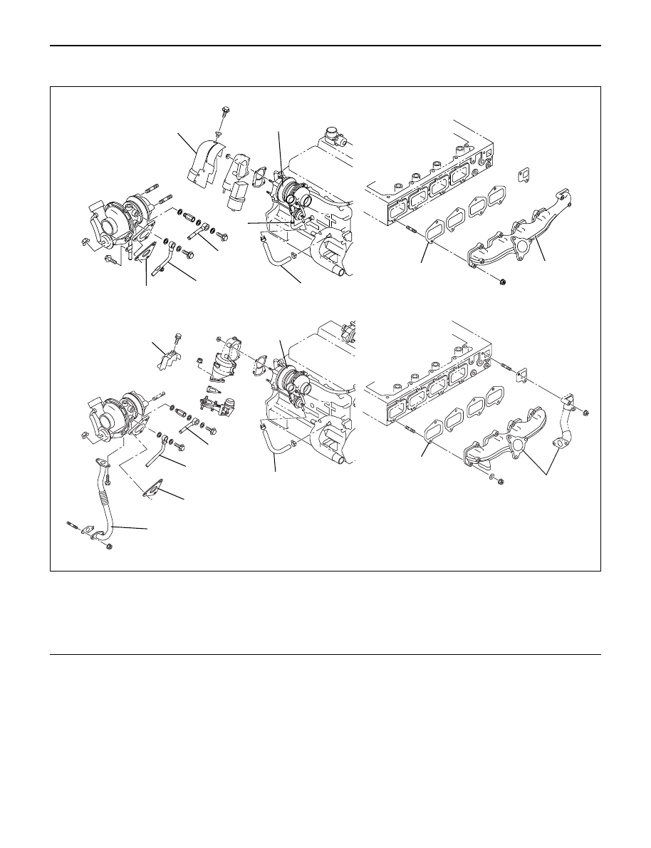
TURBOCHARGER

9

5

9

8

For Europe

8

7

5

6

3

2

1

4

7

4

2

1

3

6

025R200004

Legend

(1)

Exhaust Manifold

(2)

Gasket

(3)

Turbocharger Assembly

(4)

Water Hose

(5)

Water Hose

(6)

Heat Protector

(7)

Oil Pipe

(8)

Oil Pipe

(9)

Gasket

ENGINE MECHANICAL 6A – 39

REMOVAL

1. Remove battery.
2. Drain engine coolant.
3. Remove air cleaner cover with air duct.
4. Remove intercooler assembly.

Refer to “Intercooler” in this manual.

5. Remove water pipe for turbocharger inlet.
6. Remove oil pipe for turbocharger.

1) Remove eye bolt from turbocharger.
2) Plug oil port on the turbocharger to prevent entry

of foreign materials.

7. Remove oil drain pipe from turbocharger.
8. Remove water outlet pipe.
9. Remove heat protector.

10. Remove exhaust adaptor.
11. Remove turbocharger assembly from exhaust

manifold.

For Europe

025R200006

6A – 40 ENGINE MECHANICAL

INSTALLATION

1. Install turbocharger assembly to exhaust manifold,

tighten to the specified torque.

Torque : 27 N·m (2.8 kg·m/20 lb ft)

2. Install exhaust adaptor.

Torque : 27 N·m (2.8 kg·m/20 lb ft)

3. Install heat protector.
4. Install water outlet pipe with gasket.

Torque : 20 N·m (2.0 kg·m/14 lb ft)

5. Install turbocharger oil drain pipe.

Torque : 9 N·m (0.9 kg·m/78 lb in)

6. Install oil supply pipe to turbocharger.

1) Fill with 100 cc engine oil at the turbocharger oil

supply hole before installing the oil pipe.

2) Turn the turbocharger by hand to lubricate

turbocharger shaft.

3) Install oil supply pipe with new gasket to the

turbocharger and tighten oil supply pipe bolts to
the specified torque.

Torque : 22 N·m (2.2 kg·m/16 lb ft) for M10

54 N·m (5.5 kg·m/40 lb ft) for M14

7. Install water inlet pipe with new gasket, tighten to

the specified torque.

Torque : 20 N·m (2.0 kg·m/14 lb ft)

8. Install intercooler assembly.

Refer to “Intercooler” in this manual.

9. Install air cleaner cover with air duct, connect both

side hoses.

10. Fill with engine coolant.
11. Install the battery and connect battery cables.

For Europe

025R200007

For Europe

025R200007

For Europe

025R200006

ENGINE MECHANICAL 6A – 41

CYLINDER HEAD

3

4

1

2

012RW096

Legend

(1)

Glow Plug

(2)

Plate

(3)

Cylinder Head Bolt

(4)

Cylinder Head

NOTE: 

During disassembly, be sure that the valve train
components are kept together and identified so that
they can be re-installed in their original locations.

Before removing the cylinder head from the engine
and before disassembling the valve mechanism, do
a compression test and note the results.

DISASSEMBLY

1. Injector Assy
2. Glow Plug and Glow Plug Connector 
3. Cylinder Head Assembly

Refer to “Cylinder Head Gasket”

CLEAN

Cylinder head
Carefully remove all varnish, soot and carbon on
the bare metal. Do not use a motorized wire brush
on any gasket sealing surface.

INSPECTION AND REPAIR

Make the necessary adjustments, repairs, and part
replacements if excessive wear or damage is
discovered during inspection.

1. Cylinder head gasket and mating surfaces for

leaks, corrosion and blow-by. If the gasket has
failed, determine the cause;
– Improper installation
– Loosen or warped cylinder head
– Insufficient torque on head bolts
– Warped cylinder block surface


Content   ..  2389  2390  2391  2392   ..