Content .. 2386 2387 2388 2389 ..
Opel Frontera UBS. Manual - part 2388
6A – 26 ENGINE MECHANICAL
Illustration
Tool No.
Tool Name
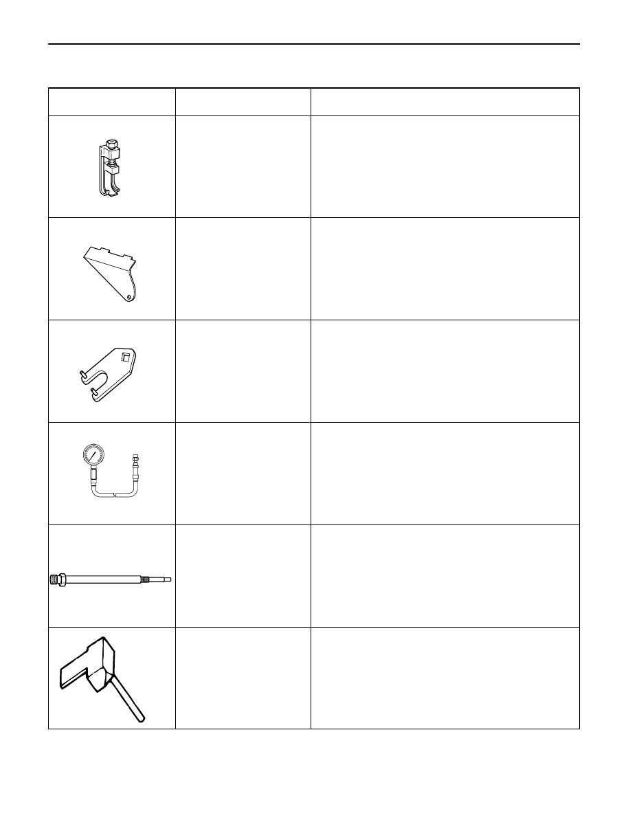
SPECIAL TOOLS
5-8840-2590-0
Valve Clearance Adjusting Tool
5-8840-2592-0
Camshaft Stopper
5-8840-2591-0
Camshaft Gear Tool
5-8840-2675-0
5-8531-7002-0
Compression Gauge
Adapter: Compression Gauge
5-8840-2153-0
Seal Cutter
kg/cm2
0
10
70
60
20
50
30
40
F06RW056
F06RV037
901LX057
901LX056
F06RW057
901RT042