Content .. 2327 2328 2329 2330 ..
Opel Frontera UBS. Manual - part 2329
6E–352
6VE1 3.5 ENGINE DRIVEABILITY AND EMISSIONS
Diagnostic Trouble Code (DTC) P1125 ETC (Electric throttle control) Limit Per-
formance Mode
D06RY00157
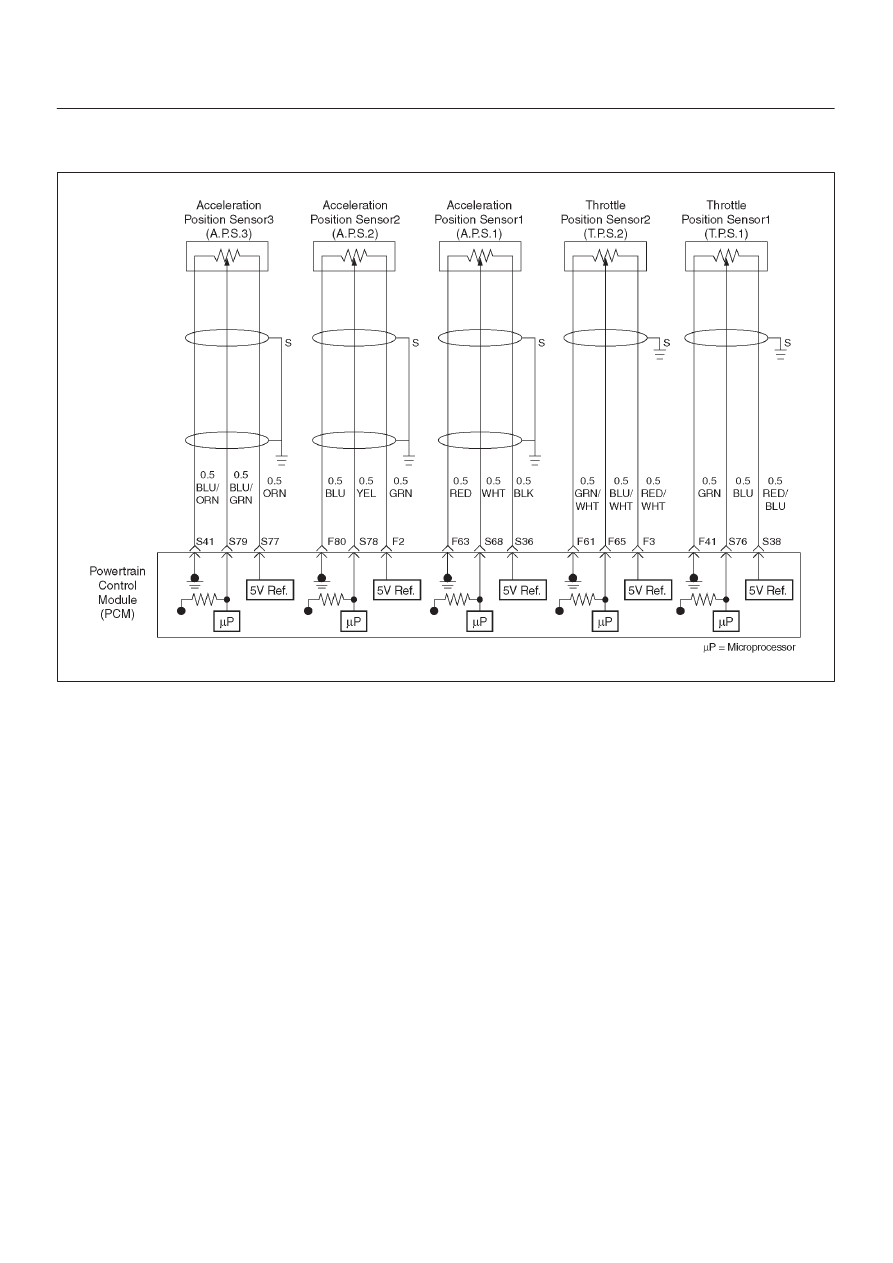
Circuit Description
D
The acceleration position (AP1) sensor circuit provides
a voltage signal relative to acceleration pedal angle.
The acceleration pedal angle will vary about 13 % at
idle position to about 87 % at wide open throttle
(WOT).
This code detects if the system is in Limit
Performance Mode (Fail safe Mode) and Multiple
DTCs performance Mode.
Conditions for setting the DTC
D
The Ignition is “ ON”.
D
Limit Performance Mode is active. (Fail safe Mode)
Action Taken When the DTC Sets
D
The PCM will store condition which were present when
the DTC was set as Freeze Frame and in the Failure
Records data.
Conditions for Clearing the MIL/DTC
D
The PCM will turn the MIL “OFF” on the third
consecutive trip cycle during which the diagnostic has
been run and the fault condition is no longer present.
D
A history DTC P1125 will clear after 40 cosecutive trip
cycle during which the warm up cycles have occurred
without a fault.
D
DTC P1125 can be cleared using the Tech 2 “Clear
Info” function or by disconnecting the PCM battery
feed.
Diagnostic Aids
An intermittent may be caused by the following:
D
Poor connectons.
D
Mis routed harness.
D
Rubbed through wire insulation.
D
Broken wire inside the insulation.
Check for the following conditions:
D
Poor connection at PCM-Inspect harness connectors
for backed out terminals, improper mating, broken
locks, improperly formed or damaged terminals,and
poor terminal to wire connection.
D
Damaged harness-Inspect the wiring harness for
damage. If the harness appears to be OK, observe the
APP sensor 1, APP sensor 2, APP sensor 3 display on
the Tech 2 While moving connectors and wiring
harnesses related to the sensor.
A change in the display will indicate the location of
the fault.
If DTC P1125 cannot be duplicated,the information
includedin the Faillure Records data can be useful in
determined vehicle mileage since the DTC was last
set.
If it is determined that the DTC occurs
intermittently,performing the DTC P1125 Diagnostic
Chart may isolate the cause of the fault.