Content .. 2263 2264 2265 2266 ..
Opel Frontera UBS. Manual - part 2265
6E–96
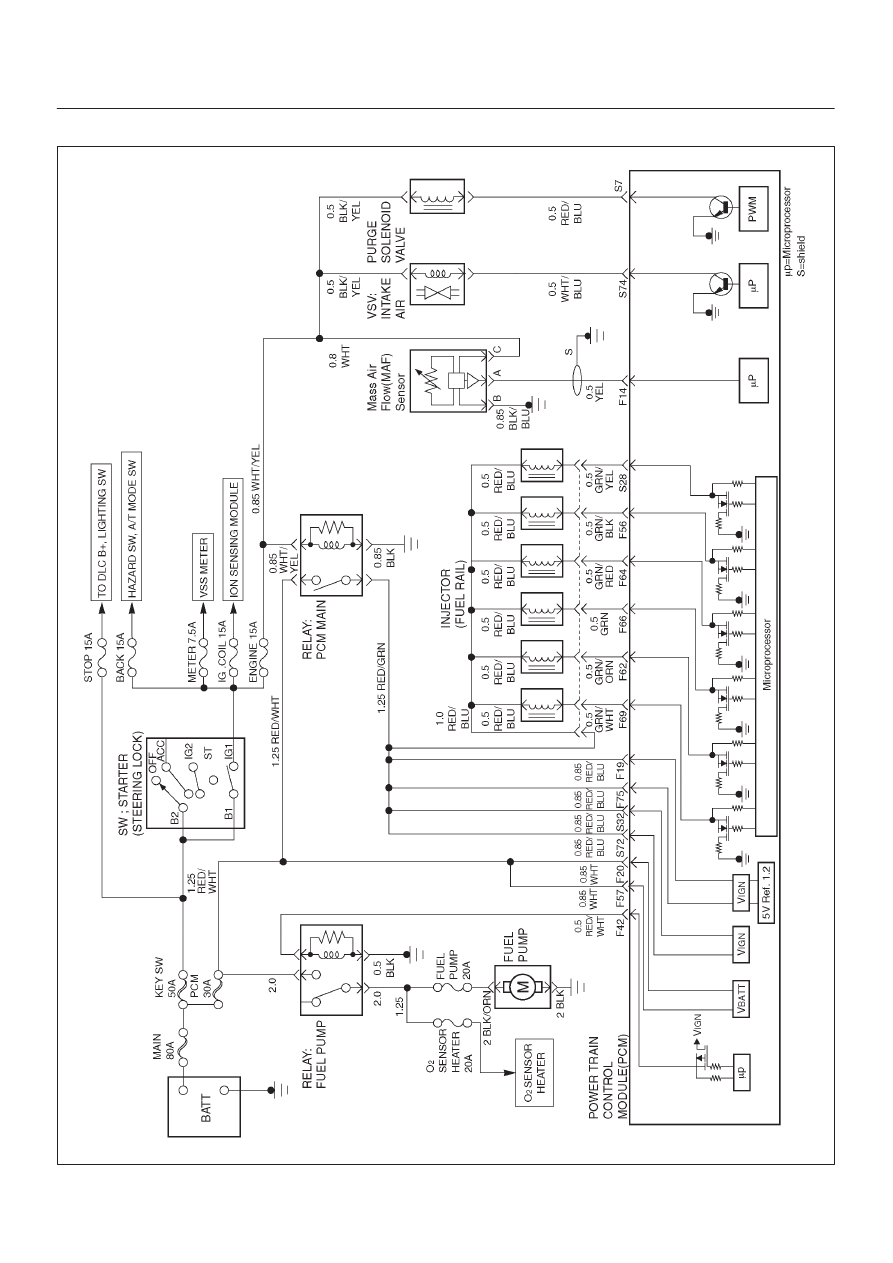
6VE1 3.5 ENGINE DRIVEABILITY AND EMISSIONS
Engine Cranks But Will Not Run
D06R200100
|
|
|
Content .. 2263 2264 2265 2266 ..
6E–96 6VE1 3.5 ENGINE DRIVEABILITY AND EMISSIONS Engine Cranks But Will Not Run D06R200100 |