Opel Frontera UBS. Manual - part 2255


  Index      Opel     Opel Frontera UBS - service repair manual 1998-2002 year


Search            


Content   ..  2253  2254  2255  2256   ..


Opel Frontera UBS. Manual - part 2255


6E–56

6VE1 3.5 ENGINE DRIVEABILITY AND EMISSIONS

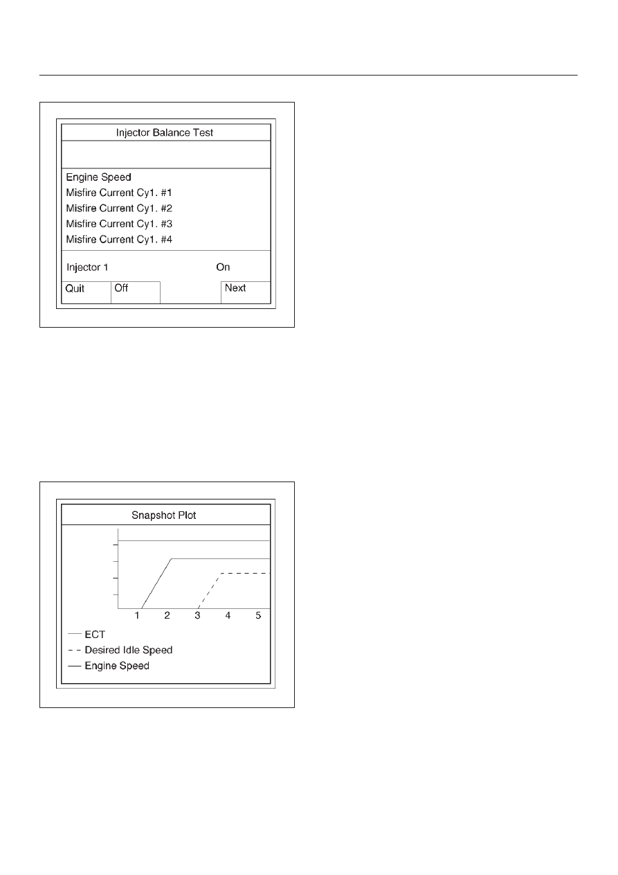
5. Select injector number and push “injector off” soft key.

060RY00105

6. Make sure of engine speed change.
7. If engine speed changes, the injector electric circuit is

normal.
If engine speed does not change, the injector electric
circuit or the injector itself is not normal.

Plotting Snapshot Graph

This test selects several necessary items from the data
list to plot graphs and makes data comparison on a long
term basis. It is an effective test particularly in emission
related evaluations.

060RX037

For trouble diagnosis, you can collect graphic data (snap
shot) directly from the vehicle.
You can replay the snapshot data as needed. Therefore,
accurate diagnosis is possible, even though the vehicle is
not available.

6E–57

6VE1 3.5L ENGINE DRIVEABILITY AND EMISSIONS

Plotting Graph Flow Chart (Plotting graph after obtaining vehicle information)

060R200070

6E–58

6VE1 3.5 ENGINE DRIVEABILITY AND EMISSIONS

Flow Chart for Snapshot Replay (Plotting Graph)

060R200072

6E–59

6VE1 3.5L ENGINE DRIVEABILITY AND EMISSIONS

Primary System-Based Diagnostic

Primary System-Based Diagnostic

There are primary system-based diagnostics which
evaluate system operation and its effect on vehicle
emissions.  The primary system-based diagnostics are
listed below with a brief description of the diagnostic
function:

Oxygen Sensor Diagnosis
The fuel control heated oxygen sensors (Bank 1 HO2S 1
and Bank 2 HO2S 1) are diagnosed for the following
conditions:

D

Heater performance (time to activity on cold start)

D

Slow response

D

Response time (time to switch R/L or L/R)

D

Inactive signal (output steady at bias voltage –
approx. 450 mV)

D

Signal fixed high

D

Signal fixed low

The catalyst monitor heated oxygen sensors (Bank 1
HO2S 2 and Bank 2 HO2S 2) are diagnosed for the
following conditions:

D

Heater performance (time to activity on cold start).

D

Signal fixed low during steady state conditions or
power enrichment (hard acceleration when a rich
mixture should be indicated).

D

Signal fixed high during steady state conditions or
deceleration mode (deceleration when a lean mixture
should be indicated).

D

Inactive sensor (output steady at approx. 438 mV).

If the oxygen sensor pigtail wiring, connector or terminal
are damaged, the entire oxygen sensor assembly must
be replaced.  DO NOT attempt to repair the wiring,
connector or terminals.  In order for the sensor to function
properly, it must have clean reference air provided to it.
This clean air reference is obtained by way of the oxygen
sensor wire(s).  Any attempt to repair the wires, connector
or terminals could result in the obstruction of the
reference air and degrade oxygen sensor performance.
Refer to 

On-Vehicle Service, Heated Oxygen Sensors in

this section.

Fuel Control Heated Oxygen Sensor

The main function of the fuel control heated oxygen
sensors is to provide the control module with exhaust
stream oxygen content information to allow proper fueling
and maintain emissions within mandated levels.  After it
reaches operating temperature, the sensor will generate
a voltage, inversely proportional to the amount of oxygen
present in the exhaust gases.  The control module uses
the signal voltage from the fuel control heated oxygen
sensors while in closed loop to adjust fuel injector pulse
width.  While in closed loop, the PCM can adjust fuel
delivery to maintain an air/fuel ratio which allows the best
combination of emission control and driveability.  The fuel
control heated oxygen sensors are also used to
determine catalyst efficiency.

HO2S Heater

Heated oxygen sensors are used to minimize the amount
of time required for closed loop fuel control to begin
operation and to allow accurate catalyst monitoring.  The
oxygen sensor heater greatly decreases the amount of
time required for fuel control sensors (Bank 1 HO2S 1 and
Bank2 HO2S 1) to become active.  Oxygen sensor
heaters are required by catalyst monitor and sensor
(Bank 1 HO2S 2 and Bank 2 HO2S 2) to maintain a
sufficiently high temperature which allows accurate
exhaust oxygen content readings further away from the
engine.

Catalyst Monitor Heated Oxygen Sensors
and Diagnostic Operation

TS24067

To control emissions of hydrocarbons (HC), carbon
monoxide (CO), and oxides of nitrogen (NOx), a
three-way catalytic converter is used.  The catalyst within
the converter promotes a chemical reaction which
oxidizes the HC and CO present in the exhaust gas,
converting them into harmless water vapor and carbon
dioxide.  The catalyst also reduces NOx, converting it to
nitrogen.  The PCM has the ability to monitor this process
using the pre-catalyst and post-catalyst heated oxygen
sensors.  The pre-catalyst sensor produces an output
signal which indicates the amount of oxygen present in
the exhaust gas entering the three-way catalytic
converter.  The post-catalyst sensor produces an output
signal which indicates the oxygen storage capacity of the
catalyst; this in turn indicates the catalyst’s ability to
convert exhaust gases efficiently.  If the catalyst is
operating efficiently, the pre-catalyst signal will be far
more active than that produced by the post-catalyst
sensor.
In addition to catalyst monitoring, the heated oxygen
sensors have a limited role in controlling fuel delivery.  If
the sensor signal indicates a high or low oxygen content
for an extended period of time while in closed loop, the
PCM will adjust the fuel delivery slightly to compensate.


Content   ..  2253  2254  2255  2256   ..