Content .. 2249 2250 2251 2252 ..
Opel Frontera UBS. Manual - part 2251
6E–40
6VE1 3.5 ENGINE DRIVEABILITY AND EMISSIONS
D
Updates the Fail Record each time the diagnostic
test fails
IMPORTANT:
Only four Fail Records can be stored.
Each Fail Record is for a different DTC. It is possible that
there will not be Fail Records for every DTC if multiple
DTCs are set.
Special Cases of Type B Diagnostic Tests
Unique to the misfire diagnostic, the Diagnostic Executive
has the capability of alerting the vehicle operator to
potentially damaging levels of misfire. If a misfire
condition exists that could potentially damage the
catalytic converter as a result of high misfire levels, the
Diagnostic Executive will command the MIL to “flash” at a
rate of once per second during those the time that the
catalyst damaging misfire condition is present.
Fuel trim and misfire are special cases of
Type B
diagnostics. Each time a fuel trim or misfire malfunction is
detected, engine load, engine speed, and engine coolant
temperature are recorded.
When the ignition is turned off, the last reported set of
conditions remain stored. During subsequent ignition
cycles, the stored conditions are used as reference for
similar conditions. If a malfunction occurs during two
consecutive trips, the Diagnostic Executive treats the
failure as a normal
Type B diagnostic, and does not use
the stored conditions. However, if a malfunction occurs
on two non-consecutive trips, the stored conditions are
compared with the current conditions. The MIL will then
illuminate under the following conditions:
D
When the engine load conditions are within 10% of
the previous test that failed.
D
Engine speed is within 375 rpm, of the previous test
that failed.
D
Engine coolant temperature is in the same range as
the previous test that failed.
Storing and Erasing Freeze Frame Data and Failure
Records
Government regulations require that engine operating
conditions be captured whenever the MIL is illuminated.
The data captured is called Freeze Frame data. The
Freeze Frame data is very similar to a single record of
operating conditions. Whenever the MIL is illuminated,
the corresponding record of operating conditions is
recorded to the Freeze Frame buffer.
Freeze Frame data can only be overwritten with data
associated with a misfire or fuel trim malfunction. Data
from these faults take precedence over data associated
with any other fault. The Freeze Frame data will not be
erased unless the associated history DTC is cleared.
Each time a diagnostic test reports a failure, the current
engine operating conditions are recorded in the
Failure
Records buffer. A subsequent failure will update the
recorded operating conditions. The following operating
conditions for the diagnostic test which failed
typically
include the following parameters:
D
Air Fuel Ratio
D
Air Flow Rate
D
Fuel Trim
D
Engine Speed
D
Engine Load
D
Engine Coolant Temperature
D
Vehicle Speed
D
TP Angle
D
AP Angle
D
MAP/BARO
D
Injector Base Pulse Width
D
Loop Status
Intermittent Malfunction Indicator Lamp
In the case of an “intermittent” fault, the MIL (“Check
Engine” lamp) may illuminate and then (after three trips)
go “OFF”. However, the corresponding diagnostic trouble
code will be stored in memory. When unexpected
diagnostic trouble codes appear, check for an intermittent
malfunction.
A diagnostic trouble code may reset. Consult the
“Diagnostic Aids” associated with the diagnostic trouble
code. A physical inspection of the applicable sub-system
most often will resolve the problem.
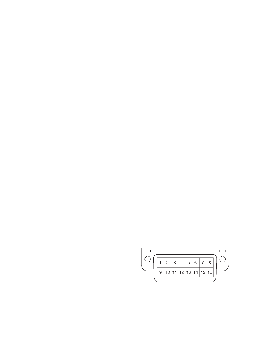
Data Link Connector (DLC)
The provision for communication with the control module
is the Data Link Connector (DLC). It is located at the
lower left of the instrument panel behind a small square
cover. The DLC is used to connect to the Tech 2 Scan
Tool. Some common uses of the Tech 2 are listed below:
D
Identifying stored Diagnostic Trouble Codes (DTCs).
D
Clearing DTCs.
D
Performing output control tests.
D
Reading serial data.
TS24064