Opel Frontera UBS. Manual - part 2242


  Index      Opel     Opel Frontera UBS - service repair manual 1998-2002 year


Search            


Content   ..  2240  2241  2242  2243   ..


Opel Frontera UBS. Manual - part 2242


6D3–25

STARTING AND CHARGING SYSTEM

Reassembly

To reassemble, follow the disassembly steps in the
reverse order, noting the following points:

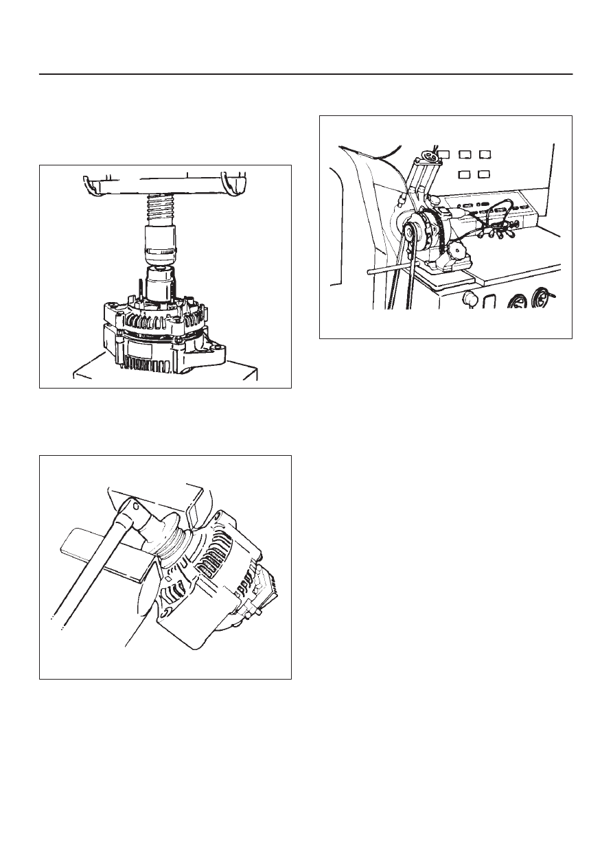
1. Using a press with a socket wrench attached,

reassemble rotor and rear end cover assembly in the
front cover.

066RS022

2. Install pulley on the rotor.

Secure the pulley directly in the vise between two
copper plates, and tighten nut to the specified torque.

Torque: 111 N·m (11.3 kg·m/82 lb ft)

066RS010

Bench Test

Conduct a bench test of the generator.

066RS023

Preparation

Remove generator from the vehicle (see “Generator
removal”).

1. Secure generator to the bench test equipment and

connect wires.
Terminal “IG” for energization
Terminal “L” for neutral (warning lamp)
Terminal “B” for output

6D3–26 STARTING AND CHARGING SYSTEM

2. Conduct the generator characteristic test.

Characteristics of generator are shown in illustration.
Repair or replace the generator if its outputs are
abnormal.

B06RX001

B06RW001

6D3–27

STARTING AND CHARGING SYSTEM

Main Data and Specifications

General Specifications

Parts Number (Nippon denso)

102211—5140

102211—1740

Model

ACHD15

ACJV74

Rated voltage

12 V

12 V

Rated output

75 A

90 A

Rotating direction (As viewed from pulled)

Clockwise

Pulley effective diameter

57.5 mm (2.26 in)

Weight

4.5 kg (9.9 lb)

5.1 kg (11.2 lb)

6E–1

6VE1 3.5L ENGINE DRIVEABILITY AND EMISSIONS

ENGINE

3.5L ENGINE DRIVEABILITY AND EMISSIONS

CONTENTS

Specifications

6E–6

. . . . . . . . . . . . . . . . . . . . . . . . . . . 

Tightening Specifications

6E–6

. . . . . . . . . . . . . . . 

Diagrams and Schematics

6E–7

. . . . . . . . . . . . . . . . 

PCM Wiring Diagram (1 of 7)

6E–7

. . . . . . . . . . . . 

PCM Wiring Diagram (2 of 7)

6E–8

. . . . . . . . . . . . 

PCM Wiring Diagram (3 of 7)

6E–9

. . . . . . . . . . . . 

PCM Wiring Diagram (4 of 7)

6E–10

. . . . . . . . . . . . 

PCM Wiring Diagram (5 of 7)

6E–11

. . . . . . . . . . . . 

PCM Wiring Diagram (6 of 7)

6E–12

. . . . . . . . . . . . 

PCM Wiring Diagram (7 of 7)

6E–13

. . . . . . . . . . . . 

PCM Pinouts

6E–14

. . . . . . . . . . . . . . . . . . . . . . . . . . . 

PCM Pinout Table, 80-Way Blue Connector
 – Row “F1 

 20”

6E–14

. . . . . . . . . . . . . . . . . . . . . . 

PCM Pinout Table, 80-Way Blue Connector
 – Row “F20 

 40”

6E–15

. . . . . . . . . . . . . . . . . . . . . 

PCM Pinout Table, 80-Way Blue Connector
 – Row “F41 

 60”

6E–17

. . . . . . . . . . . . . . . . . . . . . 

PCM Pinout Table, 80-Way Blue Connector
 – Row “F61 

 80”

6E–19

. . . . . . . . . . . . . . . . . . . . . 

PCM Pinout Table, 80-Way Red Connector
 – Row “S1 

 20”

6E–21

. . . . . . . . . . . . . . . . . . . . . . 

PCM Pinout Table, 80-Way Red Connector
 – Row “S21 

 40”

6E–23

. . . . . . . . . . . . . . . . . . . . . 

PCM Pinout Table, 80-Way Red Connector
 – Row “S41 

 60”

6E–25

. . . . . . . . . . . . . . . . . . . . . 

PCM Pinout Table, 80-Way Red Connector
 – Row “S61 

 80”

6E–27

. . . . . . . . . . . . . . . . . . . . . 

Component Locators

6E–29

. . . . . . . . . . . . . . . . . . . 

Undercarriage Component Locator

6E–31

. . . . . . 

Fuse and Relay Panel (Underhood
 Electrical Center)

6E–32

. . . . . . . . . . . . . . . . . . . . . 

Sensors and Miscellaneous Component
 Locators

6E–33

. . . . . . . . . . . . . . . . . . . . . . . . . . . . . 

Diagnosis

6E–35

. . . . . . . . . . . . . . . . . . . . . . . . . . . . . . 

Strategy-Based Diagnostics

6E–35

. . . . . . . . . . . . . 

DTC Stored

6E–35

. . . . . . . . . . . . . . . . . . . . . . . . . . . 

No DTC

6E–35

. . . . . . . . . . . . . . . . . . . . . . . . . . . . . . 

No Matching Symptom

6E–35

. . . . . . . . . . . . . . . . . 

Intermittents

6E–35

. . . . . . . . . . . . . . . . . . . . . . . . . . 

No Trouble Found

6E–35

. . . . . . . . . . . . . . . . . . . . . 

Verifying Vehicle Repair

6E–35

. . . . . . . . . . . . . . . . 

General Service Information

6E–36

. . . . . . . . . . . . . . 

OBD Serviceablity Issues

6E–36

. . . . . . . . . . . . . . . 

Visual / Physical Engine Compartment
 Inspection

6E–36

. . . . . . . . . . . . . . . . . . . . . . . . . . . . 

Basic Knowledge of Tools Required

6E–36

. . . . . . 

Serial Data Communications

6E–37

. . . . . . . . . . . . . . 

Class 2 Serial Data Communications

6E–37

. . . . . 

On-Board Diagnostic (OBD)

6E–37

. . . . . . . . . . . . . . 

On-Board Diagnostic Tests

6E–37

. . . . . . . . . . . . . 

Comprehensive Component Monitor
 Diagnostic Operation

6E–37

. . . . . . . . . . . . . . . . . . 

Common OBD Terms

6E–38

. . . . . . . . . . . . . . . . . . 

The Diagnostic Executive

6E–38

. . . . . . . . . . . . . . . 

DTC Types

6E–39

. . . . . . . . . . . . . . . . . . . . . . . . . . . 

Verifying Vehicle Repair

6E–41

. . . . . . . . . . . . . . . . 

Reading Diagnostic Trouble Codes Using
 The Tech 2 Scan Tool

6E–41

. . . . . . . . . . . . . . . . . 

Tech 2

6E–42

. . . . . . . . . . . . . . . . . . . . . . . . . . . . . . . 

Tech 2 Features

6E–43

. . . . . . . . . . . . . . . . . . . . . . . 

Getting Started

6E–43

. . . . . . . . . . . . . . . . . . . . . . . . 

Operating Procedure (For Example)

6E–44

. . . . . 

DTC Modes

6E–45

. . . . . . . . . . . . . . . . . . . . . . . . . . . 

DTC Information Mode

6E–45

. . . . . . . . . . . . . . . . . 

Miscellaneous Test

6E–46

. . . . . . . . . . . . . . . . . . . . 

Lamps Test

6E–46

. . . . . . . . . . . . . . . . . . . . . . . . . . . 

Relays Test

6E–48

. . . . . . . . . . . . . . . . . . . . . . . . . . . 

EVAP Test

6E–49

. . . . . . . . . . . . . . . . . . . . . . . . . . . . 

Fuel System Test

6E–50

. . . . . . . . . . . . . . . . . . . . . . 

Instruments Test

6E–52

. . . . . . . . . . . . . . . . . . . . . . . 

EGR Control Test

6E–53

. . . . . . . . . . . . . . . . . . . . . . 

Variable Intake Manifold Solenoid Test

6E–54

. . . 

Injector Balance Test

6E–55

. . . . . . . . . . . . . . . . . . . 

Plotting Snapshot Graph

6E–56

. . . . . . . . . . . . . . . . . 

Plotting Graph Flow Chart (Plotting graph
 after obtaining vehicle information)

6E–57

. . . . . . 

Flow Chart for Snapshot Replay
 (Plotting Graph)

6E–58

. . . . . . . . . . . . . . . . . . . . . . . 

Primary System-Based Diagnostic

6E–59

. . . . . . . . . 

Primary System-Based Diagnostic

6E–59

. . . . . . . 

Fuel Control Heated Oxygen Sensor

6E–59

. . . . . 

HO2S Heater

6E–59

. . . . . . . . . . . . . . . . . . . . . . . . . 

Catalyst Monitor Heated Oxygen Sensors
 and Diagnostic Operation

6E–59

. . . . . . . . . . . . . . 

Misfire Monitor Diagnostic Operation

6E–60

. . . . . . . 

Misfire Monitor Diagnostic Operation

6E–60

. . . . . 

Misfire Counters

6E–60

. . . . . . . . . . . . . . . . . . . . . . . 

Fuel Trim System Monitor Diagnostic
 Operation

6E–61

. . . . . . . . . . . . . . . . . . . . . . . . . . . . . . 

Fuel Trim System Monitor Diagnostic
 Operation

6E–61

. . . . . . . . . . . . . . . . . . . . . . . . . . . . 

Fuel Trim Cell Diagnostic Weights

6E–61

. . . . . . . 

On-Board Diagnostic (OBD) System Check

6E–62

Circuit Description

6E–62

. . . . . . . . . . . . . . . . . . . . . 

Diagnostic Aids

6E–62

. . . . . . . . . . . . . . . . . . . . . . . . 

SECTION


Content   ..  2240  2241  2242  2243   ..