Opel Frontera UBS. Manual - part 2063


  Index      Opel     Opel Frontera UBS - service repair manual 1998-2002 year


Search            


Content   ..  2061  2062  2063  2064   ..


Opel Frontera UBS. Manual - part 2063


5C – 64 POWER ASSISTED BRAKE SYSTEM

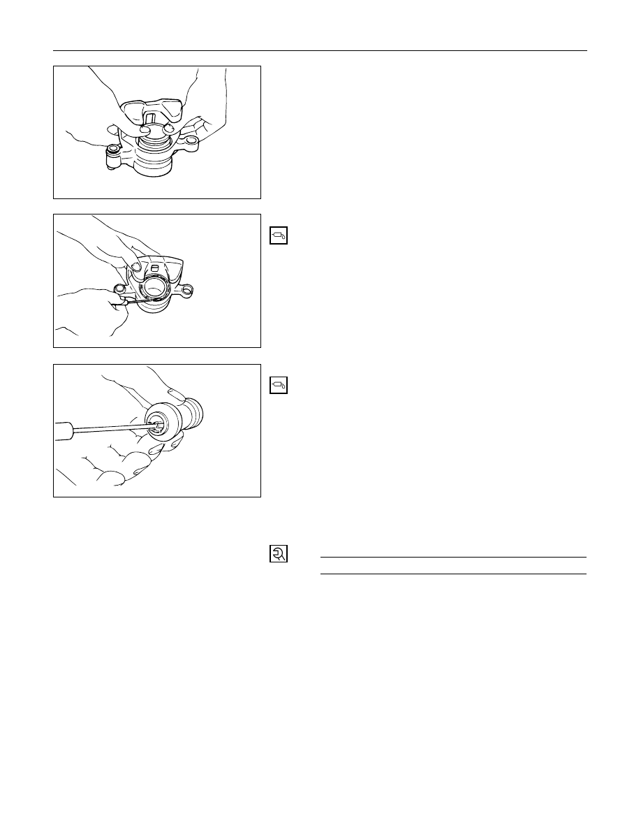
6. Dust Boot; Piston

When inserting the piston into the cylinder, use
finger pressure only. Do not use a mallet or other
impact tools, since damage to the cylinder wall or
piston seal can result.

4. Dust Boot Ring

Apply special grease (Approx. 1 g) to the piston
and attach the dust boot to the piston and caliper.
Insert the dust boot ring into the dust boot.

3. Dust Boot

Install the dust boot on the support bracket after
applying special grease (Approx 1 g) onto the
dust boot inner surface. Also apply special grease
onto the lock bolt and guide bolt setting hole of
the support bracket.

2. Lock Bolt

1. Guide Bolt

Guide Bolt Torque

N·m (kg·m / lb·ft)

44 (4.5 / 32)

POWER ASSISTED BRAKE SYSTEM  5C – 65

UNIT REPAIR

MASTER CYLINDER

The master cylinder is not repairable and must be
replaced as complete assembly if found defective.

INSPECTION

Excessive brake pedal travel, malfunction or dragging
brake suggests that the master cylinder is defective.
In such cases perform the following visual check.

Visual check
Make parts replacement as required if wear,
distortion, nicks, cuts, corrosion, or other abnormal
conditions are found through the following parts
inspection;

Master cylinder body

Fluid reservoir

O-ring

Primary piston

FUNCTIONAL INSPECTION OF MASTER
CYLINDER PISTON

Push the primary piston with your fingers to check
that it travels smoothly. If the motion is questionable,
replace the master cylinder as a complete assembly.

FUNCTIONAL INSPECTION OF MASTER
CYLINDER 

Inspect the master cylinder for function as follows. If
any abnormal function is found, replace with a new
one.
Primary piston holder: 5-8840-2306-0 (J-39242)
(including master cylinder attachment and master
cylinder plug)

Install the primary piston holder onto the master
cylinder with the spacer (2 bolts) with its adjusting
bolt screwed in up to the “0” line.

Master cylinder

Spacer

5-8840-2306-0

Primary piston holder

"0" line

"5" line

5C – 66 POWER ASSISTED BRAKE SYSTEM

Radiator cap tester: 5-8840-0277-0 (J-24460-01)

Connect master cylinder attachment with the end
of radiator cap tester, and apply air pressure with
the cap tester. Make sure there is no rise in
pressure and that with the adjusting bolt further
screwed in 5 mm (align the adjusting bolt to the
“5” line). There should be a pressure increase of
49 kpa (0.5 kg/cm

2

/7.1 psi) or more.

NOTE:
When checking the front (or primary) side, be sure to
mount master cylinder plug in the rear (or secondary)
port.

NOTE:
1) Do not use an air compressor, as the air from

compressor is mixed with compressor oil.

2) When installing the master cylinder onto the

vacuum booster, always adjust vacuum booster
push rod. (Refer to Vacuum Booster Assembly in
this section.)

3) After the master cylinder is installed onto the

vehicle, check for leakage, pedal travel and pedal
free play.

Master cylinder
plug

Master cylinder attachment

5-8840-0277-0

Radiator cap tester

5-8840-2306-0

“0” line

“5” line

Apply air

No pressure

Pressure

pressure to

rise.

increase of

the front and

49 kpa (0.5 kg/cm

2

/

rear ports

7.1 psi) more

Remarks

Check port into

Checks air

the atmospheric

tightness of the

pressure

pressure

chamber

chamber

POWER ASSISTED BRAKE SYSTEM  5C – 67

VACUUM BOOSTER

The vacuum booster cannot be disassembled for
repair. Replace a defective vacuum booster with a
new one.


Content   ..  2061  2062  2063  2064   ..