Content .. 2023 2024 2025 2026 ..
Opel Frontera UBS. Manual - part 2025
4D2–23
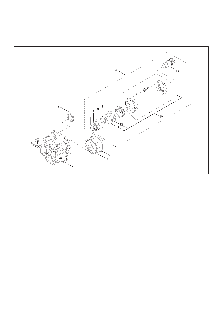
TRANSFER CASE (TOD)
Transfer Case
Disassembled View
265RW015
Legend
(1) Transfer Case
(2) Ball Bearing
(3) Ring Gear
(4) Snap Ring
(5) Input Shaft and Carrier Assembly
(6) Snap Ring
(7) Ball Bearing
(8) Snap Ring
(9) Thrust Plate
(10) Carrier Assembly
(11) Snap Ring
(12) Circular Hub
(13) Input Shaft