Opel Frontera UBS. Manual - part 2022


  Index      Opel     Opel Frontera UBS - service repair manual 1998-2002 year


Search            


Content   ..  2020  2021  2022  2023   ..


Opel Frontera UBS. Manual - part 2022


4D2–11

TRANSFER CASE (TOD)

2. Tighten the sixteen bolts to the specified torque.

Torque : 31 N·m (3.2 kg·m/23 lb ft)

3. Wind the sealing tape around the drain plug thread

and tighten the plug to the specified torque.

Torque : 25 N·m (2.5 kg·m/18 lb ft)

4. Mount the offset lever to the transfer shift and install

the spring pin.

261RW016

5. Attach the O-ring and washer to the companion

flange.

NOTE: Securely push the O-ring to the hollow of the
companion flange, and then attach the washer.

6. Use the flange holder 5-8840-0133-0 (J-8614-11) to

tighten the flange nut.

7. Tighten the flange nut to the specified torque.

Torque : 167 N·m (17.0 kg·m/123 lb ft)

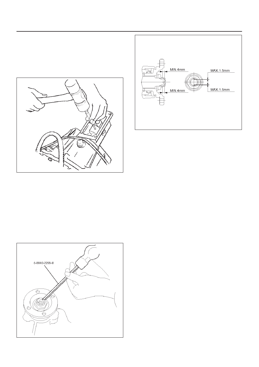
8. Using the punch 5-8840-2293-0 (J-39209), securely

stake the flange nut at two spots.

NOTE: Check the staked flange nut is free from cracks.

266RW028

260RW007

9. Fix the harness with the clip.

10. Tighten the 4L and 4H switch to the specified torque.

Torque : 24 N·m (2.4 kg·m/17 lb ft)

11. Fill the transfer case with ATF II or III (1.9 liters).

12. Wind the sealing tape around the filler plug thread and

tighten the plug to the specified torque.

Torque : 25 N·m (2.5 kg·m/18 lb ft)

4D2–12 TRANSFER CASE (TOD)

Transfer Cover Assembly

Disassembled View

261RW007

Legend

(1) Coil Assembly
(2) Snap Ring
(3) Ball Bearing

(4) Speed Gear and Tone Wheel
(5) Ball Bearing
(6) Transfer Cover Assembly
(7) Front and Rear Speed Sensors

Disassembly

1. Using snap ring pliers, remove the snap ring.

261RW047

4D2–13

TRANSFER CASE (TOD)

2. Strike the speed gear and tone wheel with a rod or

other appropriate tool from the outside of the transfer
cover assembly, and remove the ball bearing and
speed gear and tone wheel.

NOTE: Be careful not to damage the speed gear teeth.

266RW018

3. Remove the stopper plate on the back with a

precision screwdriver or other appropriate tool
starting from the small lock of the plate.

NOTE: Be careful not to damage the stopper plate during
the work.

261RW042

4. Using a terminal pull-out tool or an equivalent tool,

push down the lock to unlatch the terminal for the coil
assembly, and pull the terminal out.

NOTE: Be careful not to damage other terminals.

261RW032

5. Remove the fixing nuts of the coil assembly from the

outside of the transfer cover assembly.  Remove the
coil assembly from the transfer cover.

261RW030

4D2–14 TRANSFER CASE (TOD)

6. Using the bearing remover 5-8840-2409-0 (J-42805)

and slide hammer 5-8840-0084-0 (J-2619-01),
remove the ball bearing for the front output shaft.

901RW234

7. Remove the bolts and front and rear speed sensors.

NOTE: Be careful not to damage the speed sensors
during the work.

261RW033

Reassembly

1. Remove the oil seal from the transfer cover assembly.
2. Apply oil to the circumference of the new oil seal and

fill the lip with grease (Besco L2 or equivalent).

3. Using the oil seal installer 5-8840-2412-0 (J-42804),

install the oil seal to the transfer cover assembly.

261RW051

Rear Output Shaft Oil Seal

Distance between the transfer case end and oil seal.

NOTE: When installing the oil seal to the specified
dimension, be careful not to damage it.

Dimension : 9.85 — 10.35mm (0.39 — 0.41 in)

A04RW004


Content   ..  2020  2021  2022  2023   ..