Opel Frontera UBS. Manual - part 2005


  Index      Opel     Opel Frontera UBS - service repair manual 1998-2002 year


Search            


Content   ..  2003  2004  2005  2006   ..


Opel Frontera UBS. Manual - part 2005


4C–44

DRIVE SHAFT SYSTEM

401RW047

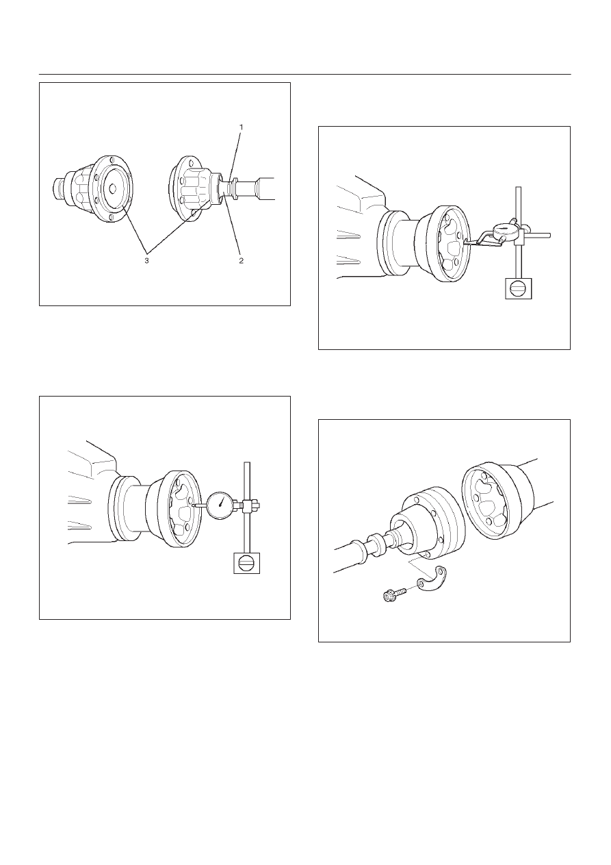
Front Axle Flange Run-out

1. Set a dial gage at right angle near the outer

circumference of the flange face and check the
run-out of the flange face.

Limit: 0.15 mm (0.006 in)

401RW046

2. Set a dial gage at right angle near the inner

circumference and check the run-out of the flange.

Limit: 0.15 mm (0.006 in)

401RW045

3. If vibration is felt during the 4H AUTO drive, disconnct

the propeller shaft at the front axle. Reinstall the
propeller shaft at 60

°

, 120

°

, 180

°

, 240

°

, and  300

°

and conduct test drive in each position and check if
there is vibration.

401RW044

4C–45

DRIVE SHAFT SYSTEM

Universal Joint Reassembly

1. Install spider to flange yoke. Be sure to install the

spider by aligning the setting marks made during
disassembly.

2. Apply a molybdenum–disulfide grease or a

multi–purpose type grease NLGI No. 2 to inside of the
bearing cap.

Grease Amount: Approx. 1.2 g (0.042 oz)

401RS011

3. Using either a mallet (or copper hammer) or a press,

install the needle roller bearing into the yoke so that
the snap ring can be installed in its groove.

CAUTION: The  needle roller bearing cannot be
installed smoothly if it is set at an incorrect angle
with the flange and excessive hammering will
damage the needle roller bearing.

401RS012

4. Align setting marks (1) and join the yokes.

401RS028

5. Install snap ring.

NOTE: Discard used snap rings and install new ones.
When the bearing cap is in position, select and attach a
snap ring of suitable thickness so that the end play of the
spider pin is held within 0.1 mm (0.004 in).

Snap ring thickness and Identification color
1.5 mm (0.059 in); Blue
1.53 mm (0.060 in); White
1.59 mm (0.063 in); Yellow
1.62 mm (0.064 in); Green
1.68 mm (0.066 in); Not colored

NOTE: Be sure to use snap rings of the same thickness
on both sides.

4C–46

DRIVE SHAFT SYSTEM

Reassembly (Except TOD 4

×

4)

401RW057

Legend

(1) Sleeve Yoke

(2) Seal
(3) Tube Assembly

1. Discard used seal and install new one.
2. Align the alignment marks and install tube assembly

to sleeve yoke.

4C–47

DRIVE SHAFT SYSTEM

Main Data and Specifications

General Specifications

Engine

6VE1 (3.5L)

6VD1 (3.2L)

4JX1 (3.0L)

4JG2 (3.1L)

Transmission

M/T

A/T

A/T

with

TOD

M/T

A/T

A/T

with

TOD

M/T

A/T

M/T

A/T

Construction

Hollow steel tube

with yoke and

spider type

universal joint

Hollow

steel

tube

with

consta

nt 

velocity

joints

Hollow steel tube

with yoke and

spider type

universal joint

Hollow

steel

tube

with

consta

nt 

velocity

joints

Hollow steel tube with yoke and 

spider type universal joint

Outside 
diameter

40.0mm (1.57 in)

Length

559mm

(22.01in)

559mm

(22.01in)

577mm

(22.72in)

393mm

(15.47in)

559mm

(22.01in)

577mm

(22.72in)

627mm

(24.69in)

627mm

(24.69in)

421mm

(16.57in)

627mm

(24.69in)

Torque Specifications

E04RW021


Content   ..  2003  2004  2005  2006   ..