Opel Frontera UBS. Manual - part 1997


  Index      Opel     Opel Frontera UBS - service repair manual 1998-2002 year


Search            


Content   ..  1995  1996  1997  1998   ..


Opel Frontera UBS. Manual - part 1997


4C–12

DRIVE SHAFT SYSTEM

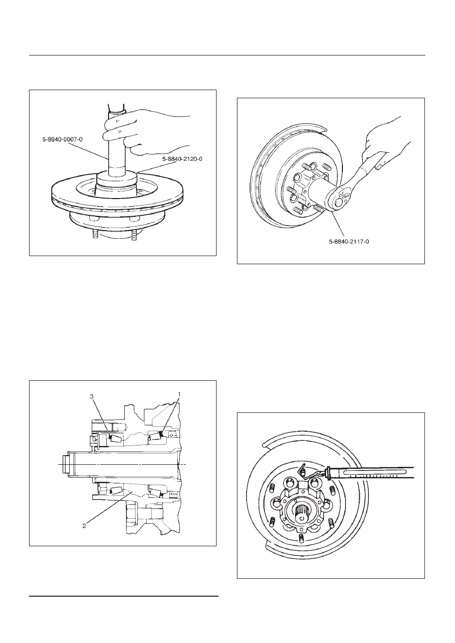
5. Apply grease (NLGI No.2 or equivalent) to the lip

portion, then install oil seal by using installer
5–8840–2120–0 and grip 5–8840–0007–0.

411RW008

6. Install ABS sensor ring, then tighten the bolts to the

specified torque.

Torque: 18 N·m (1.8 kg·m/13 lb ft)

7. Install hub and disc assembly.

D

Apply grease in the hub.

D

Apply wheel bearing type grease NLGI No. 2 or
equivalent to the outer and inner bearing.

Grease Amount
Hub: 35 g (1.23 oz)
Outer bearing: 10 g (0.35 oz)
Inner bearing: 15 g (0.53 oz)

411RS009

Legend

(1) Inner Bearing
(2) Hub
(3) Outer Bearing

8. Install hub nut. Turn the place where there is a

chamfer in the tapped hole to the outer side, then
attach the nut by using front hub nut wrench
5–8840–2117–0.

411RW005

Preload Adjustment

1. Tighten the hub nut to 29  N·m (3.0 kg·m/22 lb ft),

then fully loosen the nut.

2. Tighten the hub nut to the value given below,

using a spring scale on the wheel pin.

New bearing and New oil seal
Bearing Preload: 20 – 25 N (2.0–2.5 kg/4.4 –
5.5 lb)

Used bearing and New oil seal
Bearing Preload: 12 – 18 N (1.2–1.8 kg/2.6 –
4.0 lb)

If the measured bearing preload is outside the
specifications, adjust it by loosening or tightening the
bearing nut.

411RS011

4C–13

DRIVE SHAFT SYSTEM

9. Install lock washer and lock screw in the following

manner.

D

Turn the side with larger diameter of the tapered
bore to the vehicle outer side, then attach the
washer.

D

If the bolt holes in the lock plate are not aligned with
the corresponding holes in the nut, reverse the lock
plate.

D

If the bolt holes are still out of alignment, turn in the
nut just enough to obtain alignment.

D

Screw is to be fastened tightly so its head may
come lower than the surface of the washer.

411RS012

10. Apply adhesive (LOCTITE 515 or equivalent) to both

joining flange faces then install hub flange.

11. Install snap ring and shim.

D

Adjust the clearance between the free wheeling hub
body and the snap ring.

Clearance: 0 mm–0.3 mm (0 in–0.012 in)
Shims Available: 0.2 mm, 0.3 mm, 0.5 mm,
1.0 mm (0.008 in, 0.012 in, 0.020 in, 0.039 in)

411RW002

12. Install hub cap.
13. Tighten the bolts to the specified torque.

Torque: 59 N·m (6.0 kg·m/43 lb ft)

4C–14

DRIVE SHAFT SYSTEM

Front Hub and Disc with Manual Locking Hub

Disassembled View

411RW009

Legend

(1) Bolt
(2) Cover Assembly
(3) Gasket
(4) Knob
(5) X–ring
(6) Detent Ball and Spring
(7) Snap Ring
(8) Clutch Assembly
(9) Compression Spring

(10) Follower

(11) Retaining Spring

(12) Snap Ring and Shim

(13) Body Assembly
(14) Inner Assembly
(15) Spacer
(16) Ring
(17) Snap Ring
(18) Snap Ring
(19) Lock Washer and Lock Screw
(20) Hub Nut
(21) Hub and Disc Assembly
(22) Outer Bearing Outer Race
(23) ABS Sensor Ring (if so equipped)
(24) Inner Bearing Outer Race
(25) Oil Seal

Disassembly

1. Before disassembly, jack up the front of vehicle and

support frame with jack stands.

2. Remove the disc brake caliper assembly and hang it

on the frame with wires. Refer to Front Disk Brake
Caliper Assembly in Brakes section.

4C–15

DRIVE SHAFT SYSTEM

3. Remove bolt.

Before removal, shift transfer lever into “2H” position,
set free wheeling hub knob into “FREE” position (1),
and run the vehicle about 50m (160 ft).

411RW010

4. Remove cover assembly.
5. Remove snap ring and shim.
6. Remove body assembly.
7. Remove lock washer and lock screw.
8. Remove hub nut by using wrench 5–8840–2117–0.

411RW005

9. Remove hub and disc assembly.

10. Remove ABS sensor ring (If equipped).

11. Remove outer bearing outer race.

12. Remove oil seal.

13. Remove inner bearing outer race.
14. While pushing follower knob against cover, turn clutch

assembly clockwise and then remove clutch
assembly from knob.

411RW011

15. Remove gasket.
16. Remove snap ring.
17. Remove knob.
18. Remove compression spring.
19. Remove follower.
20. Remove retaining spring from clutch assembly by

turning it counterclockwise.

411RW012

21. Remove dedent ball and spring.
22. Remove X–ring.
23. Remove snap ring.
24. Remove inner assembly.
25. Remove snap ring.
26. Remove ring.
27. Remove spacer.


Content   ..  1995  1996  1997  1998   ..