Opel Frontera UBS. Manual - part 199


  Index      Opel     Opel Frontera UBS - service repair manual 1998-2002 year


Search            


Content   ..  197  198  199  200   ..


Opel Frontera UBS. Manual - part 199


5A–9

BRAKE CONTROL SYSTEM

Getting Started

D

Before operating the Isuzu PCMCIA card with the
Tech 2, the following steps must be performed:

1. The Isuzu 98 System PCMCIA card (1) inserts into

the Tech 2 (4).

2. Connect the SAE 16/19 adapter (2) to the DLC cable

(3).

3. Connect the DLC cable to the Tech 2 (4).
4. Make sure the vehicle ignition is off.
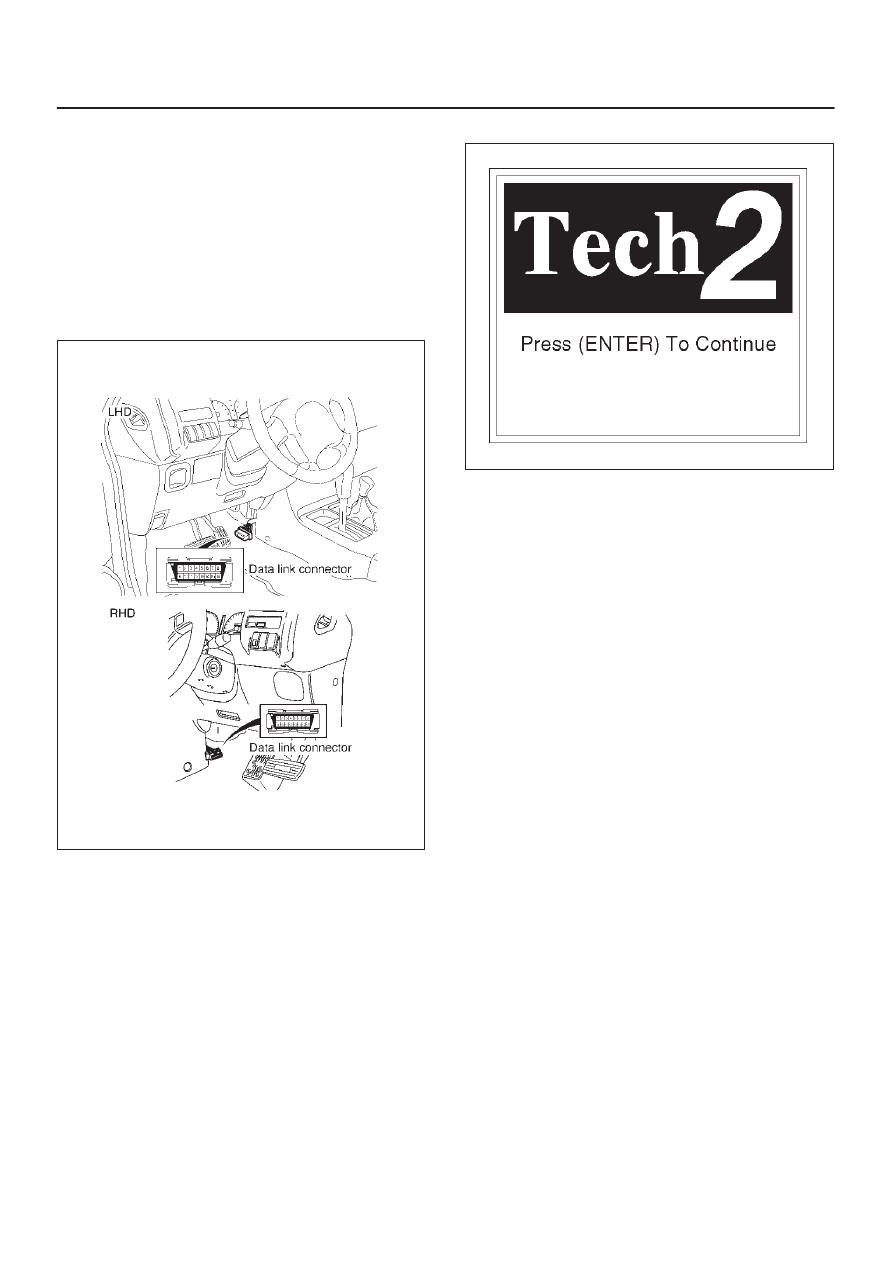
5. Connect the Tech 2 SAE 16/19 adapter to the vehicle

DLC connector.

350RV014

6. The vehicle ignition turns on.
7. Power up the Tech 2.

8. Verify the Tech 2 power up display.

060RW009

5A–10

BRAKE CONTROL SYSTEM

Operating Procedure

The power up screen is displayed when you power up the
tester with the Isuzu systems PCMCIA card. Follow the
operating procedure below.

060RW014

060RW020

5A–11

BRAKE CONTROL SYSTEM

Data List

Display

Content

OK/NG Criteria for Data

Battery Voltage

Voltage

D

Between 10-16.9V

Brake Light Switch

Open/Close

D

Open(0V) when pedal is released

D

Closed(12V) when pedal is depressed.

Front Left Wheel Speed
Front Right Wheel Speed
Rear Left Wheel Speed
Rear Right Wheel Speed

MPH(km/h)

D

Start the vehicle and make sure of linear change in each
wheel speed.

D

Turn each wheel by hand and make sure that each
speed data change.

Wheel Sensor Status

OK/NG

D

To be OK usually

G-sensor

Low/High

D

To be Low usually

Transfer Monitor(TOD)

2 Wheel Drive
4 Wheel Drive

D

When 2WD: 2 Wheel Drive

D

When 4WD: 4 Wheel Drive

Off-Road Switch
(Transmission Input)

Active/Inactive

D

When shift lever position is 1, 2 and R: Active (M/T)

(Transmission Input)

D

When shift lever position is L and R: Active (A/T)

Valve Relay

Active/Inactive

D

To be Active usually

ABS State

ON/OFF

D

To be OFF usually

ABS Relay

Active/Inactive

D

To be Active usually

Return Pump Relay

Active/Inactive

D

To be Inactive usually

Front Left Isolation Valve

Active/Inactive

D

To be Inactive usually

Front Left Dump Valve

Front Right Isolation Valve

Front Right Dump Valve

Rear Isolation Valve

Rear Dump Valve

ABS Warning Lamp

ON/OFF

D

To be ON usually (while engine stopped)

5A–12

BRAKE CONTROL SYSTEM

EHCU Connector Pin-out Checks

D

Disconnect Electronic Brake Control Module.

D

Perform checks with high impedance digital
multimeter (5-8840-0366-0) or equivalent.

No.

Circuit to be Tested

Ignition

Switch

Position

Multimeter

Scale/Range

Measure 

between 

Pin Number

Nominal Value

Note

1

Ignition enable

OFF

20DCV

8 (+), 15 (–)

0V to 0.1V

ON

20DCV

8 (+), 15 (–)

11.5V to 14.5V

2

Stop light switch

OFF

20DCV

10, 15

10.5V to 14.5V

Press brake pedal

3

Ground connection

OFF

200

W

12, Ground
15, Ground

Less than 2

W

4

FL speed sensor

OFF

2k

W

20, 21

1.3k to 1.9k

W

Internal Resistance

OFF

200k

W

20, 15

more than

100k

W

Insulation Resistance

OFF

200mACV

20, 21

more than

200mV

Turn wheel at 1RPS

5

FR speed sensor

OFF

2k

W

4, 5

1.3k to 1.9k

W

Internal Resistance

OFF

200k

W

4, 15

more than

100k

W

Insulation Resistance

OFF

200mACV

4, 5

more than

200mV

Turn wheel at 1RPS

6

RL speed sensor

OFF

2k

W

22, 23

1.3k to 1.9k

W

Insulation Resistance

OFF

200k

W

22, 15

more than

100k

W

Internal Resistance

OFF

200mACV

22, 23

more than

200mV

Turn wheel at 1RPS

7

RR speed sensor

OFF

2k

W

2, 3

1.3k to 1.9k

W

Internal Resistance

OFF

200k

W

2, 15

more than

100k

W

Insulation Resistance

OFF

200mACV

2, 3

more than

200mV

Turn wheel at 1RPS

8

G-sensor

ON

26,8

1k to 2k

W

Horizontal vehicle

9

Transmission Input

ON

20DCV

6 (+), 15 (–)

Less than 6V

(Shift lever

position – L, R)

6.6 to 9.0V

(other shift

position)

A/T
Battery voltage 12V

More than 9.6V

(Shift lever

position – 

1, 2, R)

6.6 to 9.0V

(other shift

position)

M/T
Battery voltage 12V


Content   ..  197  198  199  200   ..