Content .. 1982 1983 1984 1985 ..
Opel Frontera UBS. Manual - part 1984
4B2–83
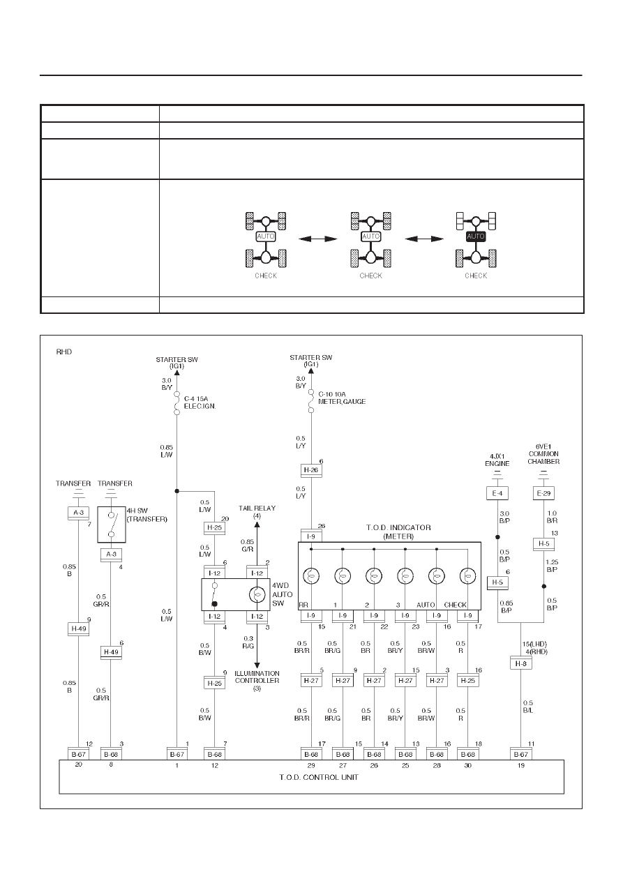
DRIVE LINE CONTROL SYSTEM (TOD)
Chart C–1
4H switch circuit wires are broken or the battery is short-circuited.
Function of circuit
—
Fail condition
When the 4WD AUTO SW is 4WD mode.
When the lever is shifted from 4L to HIGH, the 4L mode remains on the indicator and the
TOD mode is displayed without turning off the previous mode.
Indicator lamp status
Transfer position
4L <——> Neutral <——> TOD
D04RY00114