Content .. 1974 1975 1976 1977 ..
Opel Frontera UBS. Manual - part 1976
4B2–51
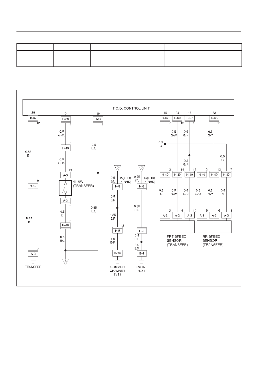
DRIVE LINE CONTROL SYSTEM (TOD)
Check flow
Trouble code
Phenomenon
Standard
5
24
(P1733)
Rear speed sensor signal open or
GND short, speed sensor COM
open.
0.3V > sensor voltage
NOTE: The following procedure shows the case that the
front or rear sensor reference or common grounding line
is broken.
D04RY00059