Opel Frontera UBS. Manual - part 1941


  Index      Opel     Opel Frontera UBS - service repair manual 1998-2002 year


Search            


Content   ..  1939  1940  1941  1942   ..


Opel Frontera UBS. Manual - part 1941


DIFFERENTIAL (REAR 220mm) 4A2A–25

4. Remove the cross pin, using a soft metal rod and a

hammer.

425RS043

5. Remove pinion gear.
6. Remove side gear.
7. Remove thrust washer.

Inspection and Repair

Make necessary correction or parts replacement if wear,
damage, corrosion or any other abnormal conditions are
found through inspection.
Check the following parts:

1. Ring gear, pinion gear
2. Bearing
3. Side gear, pinion gear, cross pin
4. Differential cage, carrier
5. Thrust washer
6. Oil seal

Ring gear replacement:

1. The ring gear should always be replaced with the

drive pinion as a set.

2. Clean the ring gear threaded holes to remove the

locking agent.

3. When installing the ring gear, apply LOCTITE 271 or

equivalent to all the threaded area and half of the
unthreaded area of the bolt.

4. Discard used bolts and install new ones.

Torque: 108 N·m (11.0kg·m/80 lb ft)

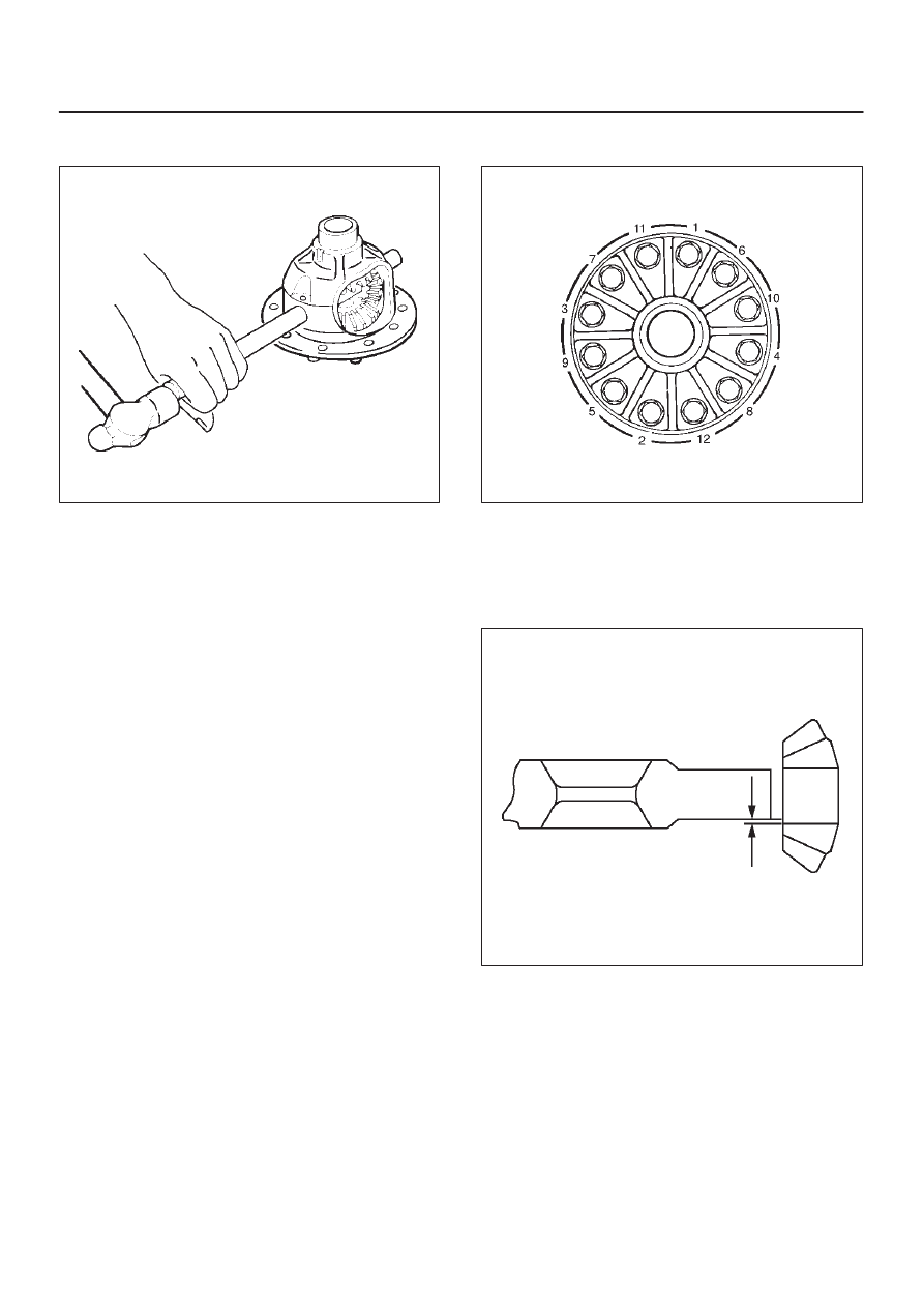
5. Tighten the fixing bolts in a diagonal sequence as

illustrated.

415RW036

Clearance between the differential pinion
and the cross pin measurement:

Standard: 0.06 – 0.12 mm (0.002–0.005 in)

Limit: 0.2 mm (0.008 in)

425RS045

4A2A–26 DIFFERENTIAL (REAR 220mm)

Clearance between the side gear and the
differential box:

Standard: 0.05–0.12 mm (0.002–0.005 in)

Limit: 0.15 mm(0.006 in)

425RS046

Legend

(1) Side Gear
(2) Differential Box

Play in splines between the side gear and
the axle shaft: 

Standard: 0.07–0.38 mm(0.003 –0.014 in)

Limit:0.5m (0.02 in)

425RS047

Reassembly

1. Install thrust washer.
2. Install side gear.
3. Install the pinion gear by engaging it with the side

gears while turning both pinion gears simultaneously
in the same direction.

425RS048

4. Install cross pin.

1. Be sure to install the cross pin so that it is in

alignment with the lock pin hole in the differential
cage.

425RS049

2. Adjust the backlash between the side gear and

the pinion gear.

Backlash:0.13 – 0.18 mm (0.005– 0.007 in)

DIFFERENTIAL (REAR 220mm) 4A2A–27

Thickness of thrust washers available:

0.80 mm, 0.90 mm, 1.00 mm 1.10 mm, 1.20 mm,
1.30 mm (0.031 in, 0.035 in, 0.039 in,0.043 in,
0.047 in, 0.051 in)

425RS050

5. Install lock pin. After lock pin installation, stake the

cage to secure the lock pin.

425RS051

Legend

(1) Staked Portion
(2) Lock Pin

6.  Clean the ring gear threaded holes to remove the

locking agent. When installing the ring gear, apply
LOCTITE 271 or equivalent to all the threaded area
and half of the unthreaded area of the bolt.

7. Tighten the bolts in diagonal sequence as illustrated.

Torque: 108 N·m (11.0kg·m/80 lb ft)

NOTE: Discard used bolts and install new ones.

415RW036

4A2A–28 DIFFERENTIAL (REAR 220mm)

Limited Slip Differential

Disassembled View

425RY001

Legend

(1) Screw
(2) Differential cage A
(3) Thrust washer
(4) Spring disc
(5) Friction Plate
(6) Friction plate
(7) Friction Plate 
(8) Friction disc
(9) Friction Plate 

(10) Friction disc 

(11) Friction Plate 

(12) Pressure ring
(13) Side gear

(14) Pinion and Pinion shaft 
(15) Side gear
(16) Pressure ring
(17) Friction Plate
(18) Friction disc
(19) Friction Plate 
(20) Friction disc
(21) Friction Plate 
(22) Friction Plate 
(23) Friction Plate 
(24) Spring disc 
(25) Thrust washer 
(26) Differential cage B 


Content   ..  1939  1940  1941  1942   ..