Opel Frontera UBS. Manual - part 1887


  Index      Opel     Opel Frontera UBS - service repair manual 1998-2002 year


Search            


Content   ..  1885  1886  1887  1888   ..


Opel Frontera UBS. Manual - part 1887


COMPRESSOR OVERHAUL  1D – 19

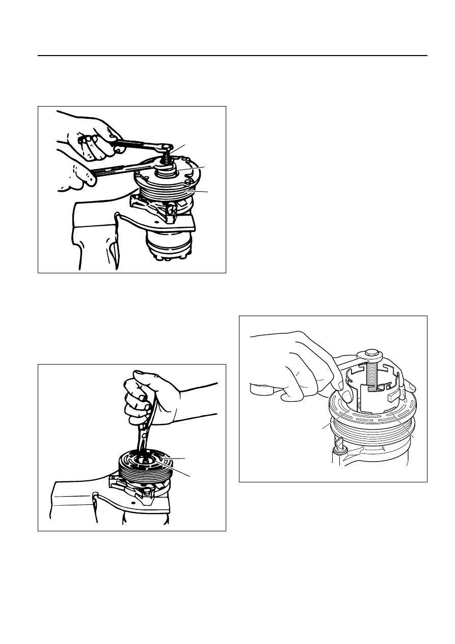
CAUTION: If the center screw is threaded fully onto
the end of the compressor shaft. or if the body of
the installer is held and the center screw is rotated,
the key will wedge and will break the clutch hub.

7. Remove installer J-33013-B, check for proper

positioning of the shaft key (even or slightly above
the clutch hub).

8. Spin the pulley rotor by hand to see that the rotor is

not rubbing the clutch drive plate.

COMPRESSOR CLUTCH ROTOR AND/OR
BEARING

Removal

1. Remove the clutch plate and hub assembly as

described previously.

2. Remove rotor (1) and bearing assembly retaining

ring (2), using snap ring pliers.

3. Install pulley rotor and bearing puller guide J-33023-A

to the front head and install J-41552 pulley rotor and
bearing puller down into the inner circle of slots (1) in
the rotor. Turn the J-41552 puller clockwise in the
slots in the rotor.

4. Hold the J-41552 puller in place and tighten the

puller screw against the puller guide to remove the
pulley rotor and bearing assembly.

Installation

1. With the compressor mounted to the J-34992

holding fixture, position the rotor and bearing
assembly on the front head.

2. Position the J-33017 pulley, rotor and bearing

installer and J-33023-A puller pilot directly over the
inner race of the bearing.

1

2

J-33013-B

901RW002

1

2

901RW003

J-41552

1

871RW007

1D – 20 COMPRESSOR OVERHAUL

3. Position puller crossbar J-8433-1 on the puller pilot

J-33023-A and assemble the two J-33026 through
bolts and washers through the puller bar slots and
thread them into the J-33026 holding fixture. The
thread of the through bolts should engage the full
thickness of the holding fixture.

4. Tighten the center screw in the J-8433-1 puller

crossbar to force the pulley rotor (1) and bearing
assembly onto the compressor front head. Should
the J-33017 pulley rotor and bearing installer slip off
direct in-line contact with the inner race of the
bearing, loosen the J-8433-1 center forcing screw
and realign the installer and pilot so that the J-
33017 installer will properly clear the front head.

5. Install rotor and bearing assembly retainer ring,

using snap ring pliers.

6. Reinstall clutch plate and hub assembly as

described previously.

COMPRESSOR CLUTCH COIL

Removal

1. Perform Steps 1 through 4 of "Clutch Rotor and/or

Bearings" removal procedure. Mark clutch coil
terminal location (1) on compressor front head.

2. Install J-33023-A puller pilot on front head of

compressor. Also install J-8433-1 puller crossbar
with J-33025 puller legs as shown in figure.

3. Tighten J-8433-3 forcing screw against the puller

pilot to remove the clutch coil (2).

J-8433-3

J-33023

J-33026

J-8433-1

J-33017

1

901RW005

J-33023-A

J-8433-3

J-8433-1

J-33025

1

2

901RW006

COMPRESSOR OVERHAUL  1D – 21

Installation

1. Place the clutch coil assembly (1) on the front head

with the terminals positioned at the "marked" location.

2. Place the J-33024 clutch coil installer over the

internal opening of the clutch coil housing and align
installer with the compressor front head.

3. Center the J-8433-1 puller crossbar in the counter-

sunk center hole of the J-33024 clutch coil installer.
Install the J-33026 through bolts and washers
through the crossbar slots and thread them into the
holding fixture J-33026 to full fixture thickness.

4. Turn the center forcing screw of J-8433-1 puller

crossbar to force the clutch coil onto the front head.
Be sure clutch coil and J-33024 installer stay "in-
line" during installation.

5. When coil is fully seated on the front head, use a

1/8 in diameter drift punch (2) and stake the front
head at three places 120 degrees apart, to ensure
clutch coil (3) remains in position.

Stake size should be only one-half the area of the
punch tip and be only approximately 0.28–0.35
mm (.010–.015 in) deep.

Legend

(1)

Stake Front Head 0.28–0.35 mm Deep
(0.10–015 in)

(2)

Clutch Coil Housing

(3)

Front Head Surface

6. Install rotor and bearing assembly and the clutch

plate and hub assembly as described previously.

J-8433-3

J-8433-1

J-33024

1

901RW007

2

3

871RW004

1

2

3

871RW005

1D – 22 COMPRESSOR OVERHAUL

COMPRESSOR SHAFT SEAL

Service Precaution

When replacing the shaft seal assembly, pressure relief
valve or control switches, it will be necessary to recover
the refrigerant. Other than clutch repair procedures, the
same holds true for any disassembly of the compressor.
A clean workbench covered with a sheet of clean
paper, and a place (clean trays, etc) for all parts being
removed and replaced is important, as is the use of
proper clean service tools.

CAUTION: Any attempt to use makeshift or
inadequate service tools or equipment may result
in damage and/or improper compressor operation.

All parts required for servicing the internal compressor
are protected by a preservative process and packaged
in a manner which will eliminate the necessity of
cleaning, washing or flushing of the parts. The parts
can be used in the internal assembly just as they are
removed from the service package. Seals and
protective packaging should be left intact until just
prior to installation.
If the compressor rear head, front head or cylinder and
shaft assembly is to be serviced or replaced, the oil in
the compressor must be drained, measured, recorded
and replaced.

Legend

(1)

Suction Port

(2)

Discharge Port

(3)

Mounting Boss

(4)

Mounting Boss

(5)

Pressure Relief Valve

(6)

Mounting Boss

Seal Leak Detection

A shaft seal should not be changed because of small
amounts of oil found on an adjacent surface but only
after actual refrigerant leakage is found using an
approved leak detector.

CAUTION: Handling and care of seal protector is
important. If seal protector is nicked or the bottom
flared, the new seal may be damaged during
installation.

Removal

1. Recover the refrigerant using Refrigerant Recovery

System.

2. Loosen and reposition compressor in mounting

brackets, if necessary.

3. Remove clutch plate and hub assembly from

compressor as described previously.

4. Remove the shaft seal retainer ring, using snap ring

pliers.

5. Thoroughly clean inside of compressor neck area

surrounding the shaft, the exposed portion of the
seal, the retainer ring groove and the shaft itself.
Any dirt or foreign material getting into compressor
may cause damage.

6. Fully engage the knurled tangs of Seal Remover-

Installer J-23128-A into the recessed portion of the
Seal (1) by turning the handle clockwise. Remove
the Seal from the compressor with a rotary-pulling
motion.
Discard the seal. The handle must be hand-
tightened securely. Do not use a wrench or pliers.

1

2

3

4

5

6

871RW006

J-23128-A

1

901RW008


Content   ..  1885  1886  1887  1888   ..