Opel Frontera UBS. Manual - part 1881


  Index      Opel     Opel Frontera UBS - service repair manual 1998-2002 year


Search            


Content   ..  1879  1880  1881  1882   ..


Opel Frontera UBS. Manual - part 1881


AIR CONDITIONING  1B–125
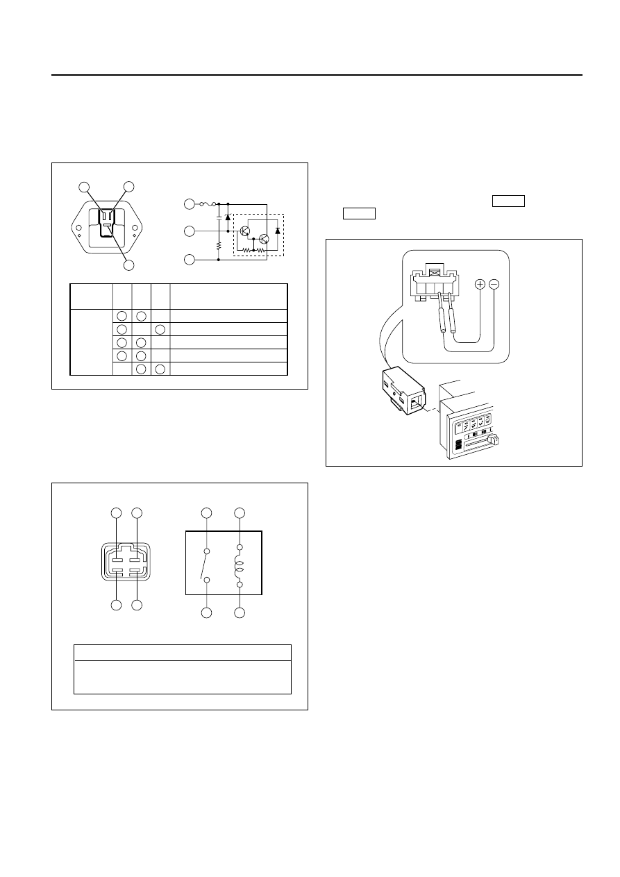
Power Transistor

1. Remove the power transistor connector (I-47)

from the evaporator assembly.

2. Check the conduction between the power

transistor side terminals.

MAX HI Relay

1. Remove the MAX HI relay connector (B-64) from

the blower assembly.

2. Check the conduction between the MAX HI relay

side terminals.

In Car Sensor

1. Turn on the ignition switch (the engine is

started). Start the air conditioner in "Full Auto".

2. Make sure that the in car sensor suctions

cigarette smokes and such.

3. Dismount the in car sensor from the automatic

heater/air conditioner control unit. Connect (+)
end and (-) end of the battery to the aspirator
motor side terminals No.1 

and No.2

, respectively, then

check if the motor runs normally.

I-34

I-34

20       25       30

AUTO

4 3 2 1

C01RW020

4

3

3

4

1

2

2

1

No continuity between terminals (2) and (4).

Continuity between terminal (2) and (4) when battery 

voltage is applied between (1) and (3).

C01RY00003

1

2

3

Terminal
No.

Conduction

Conducted (50‰ maximum)

Conducted (100‰ maximum)

Conducted (220‰ maximum)

Not conducted

Not conducted

1

2

3

Testing
rod

1

2

3

C01RY00002

1B–126 AIR CONDITIONING

ON-VEHICLE SERVICE

Power Transistor

Legend

(1)

Evaporator Assembly

(2)

Passenger Knee Bolster Reinforcement

(3)

Lower Cluster

(4)

Front Console

(5)

Glove Box

(6)

Instrument Panel Passenger Lower Cover

(7)

Power Transistor Connector

(8)

Power Transistor

Removal

1. Remove front console.

2. Remove lower cluster.

3. Remove glove box.

4. Remove instrument panel passenger lower

cover.

5. Remove passenger knee bolster reinforcement.

6. Disconnect the power transistor connector.

7. Remove power transistor.

Installation

To install, follow the removal step in the reverse
order.

Automatic Heater/Air Conditioner Control
Unit

Legend

(1)

Connector

(2)

Automatic Heater / Air Conditioner Control
Unit

(3)

Instrument Panel Cluster

(4)

Set Screw

Removal

1. Disconnect the battery ground cable.

2. Remove instrument panel cluster.

Refer to Instrument Panel Assembly in Body
Structure section.

3. Disconnect the automatic heater / air conditioner

control unit connector.

4. Remove automatic heater/ air conditioner

control unit.

Installation

To install, follow the removal step in the reverse
order.

7

6

5

4

3

2

8

1

874RY00001

This illustration is based on RHD

20       2

5       3

0

ZEXEL

AUTO

A/C

OF

F AUTO LO

HI

3

2

4

1

865RY00007

This illustration is based on RHD

AIR CONDITIONING  1B–127

In Car Sensor

Legend

(1)

In Car Sensor

(2)

Automatic Heater / Air Conditioner Control
Unit

Removal

1. Disconnect the battery ground cable.

2. Remove the automatic heater / air conditioner

control unit.

Refer to the automatic heater / air conditioner
control unit section.

3. Remove in car sensor.

Installation

To install, follow the removal step in the reverse
order.

Ambient Sensor

Legend

(1)

Ambient Sensor

(2)

Sensor Connector

(3)

Radiator Grill

Removal

1. Disconnect the battery ground cable.

2. Remove radiator grille.

Refer to Radiator Grille in Body Structure
section.

3. Disconnect the ambient sensor connector.

4. Remove the ambient sensor.

Installation

To install, follow the removal step in the reverse
order.

20

25

30

ZEX

EL

AUTO

A/C

OFF

AUTO

LO

HI

2

1

865RY00006

1

2

3

875RY00001

1B–128 AIR CONDITIONING

Sun Sensor

Legend

(1)

Sun Sensor

Removal

1. Disconnect the battery ground cable.

2. Remove the sun sensor.

3. Disconnect the sun sensor connector.

Installation

To install, follow the removal step in the reverse
order.

Electronic Thermostat

Legend

(1)

Duct Sensor

(2)

Thermostat Assembly

(3)

Evaporator Assembly

Removal

1. Disconnect the battery ground cable.

2. Remove evaporator assembly.

Refer to Evaporator Assembly section.

3. Remove electronic thermostat.

Installation

To install, follow the removal step in the reverse
order.

1

826RY00001

1

3

2

874RY00002

This illustration is based on RHD

This illustration is based on RHD


Content   ..  1879  1880  1881  1882   ..