Content .. 1841 1842 1843 1844 ..
Opel Frontera UBS. Manual - part 1843
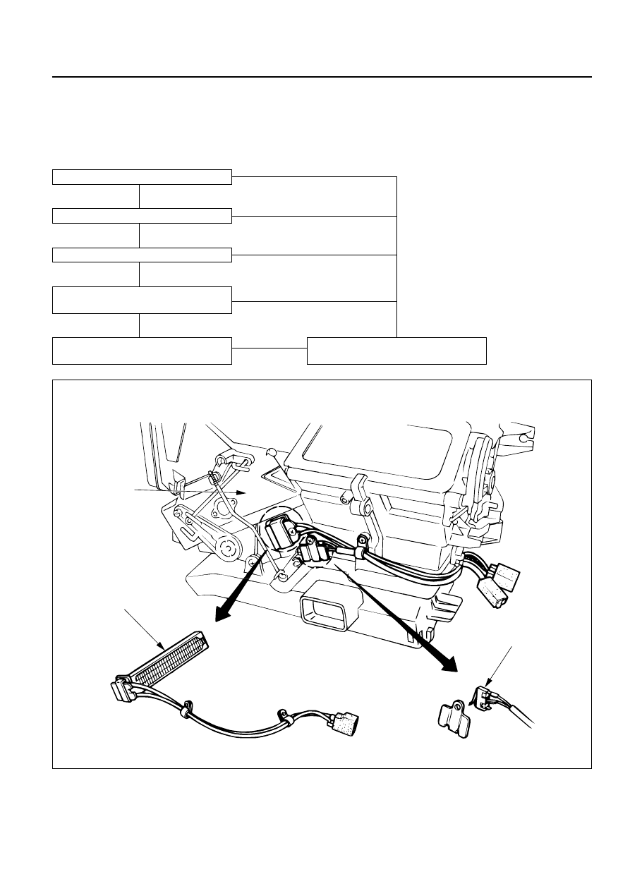
Full hot switch
Ceramic heater
Heater unit
HEATING AND VENTILATION 1A – 5
CERAMIC HEATER
When the fan control knob (fan switch) turns on with the temperature control knob set to “FULL HOT” (full
hot switch “ON”), the ceramic heater in the heater unit gets hot, thus causing the heater blow temperature
of diesel vehicle to get high to improve the heating performance (Since the engine coolant temperature of
diesel vehicle is low, its blow temperature is also low.).
Glow plug
Full hot switch
Fan switch
Thermo switch
Less than 80°C (177.8°F)
CERAMIC HEATER
“ON”
CERAMIC HEATER
“OFF”
OFF
ON
OFF
OFF
OFF
ON
ON
ON
This illustration is based on RHD