Opel Frontera UBS. Manual - part 1803


  Index      Opel     Opel Frontera UBS - service repair manual 1998-2002 year


Search            


Content   ..  1801  1802  1803  1804   ..


Opel Frontera UBS. Manual - part 1803


SUPPLEMENTAL RESTRAINT SYSTEM

9J–42

CAUTION: Never use the air bag assembly from
another vehicle. Use only new air bag assembly
proper to the Trooper which is being repaired.

827RT008

13. Enable the SRS (Refer to “Enabling the SRS” in this

section).

SRS Coil Replacement Procedure

Removal

1. Same removal steps until step 13 of SRS Coil

Assembly Removal.

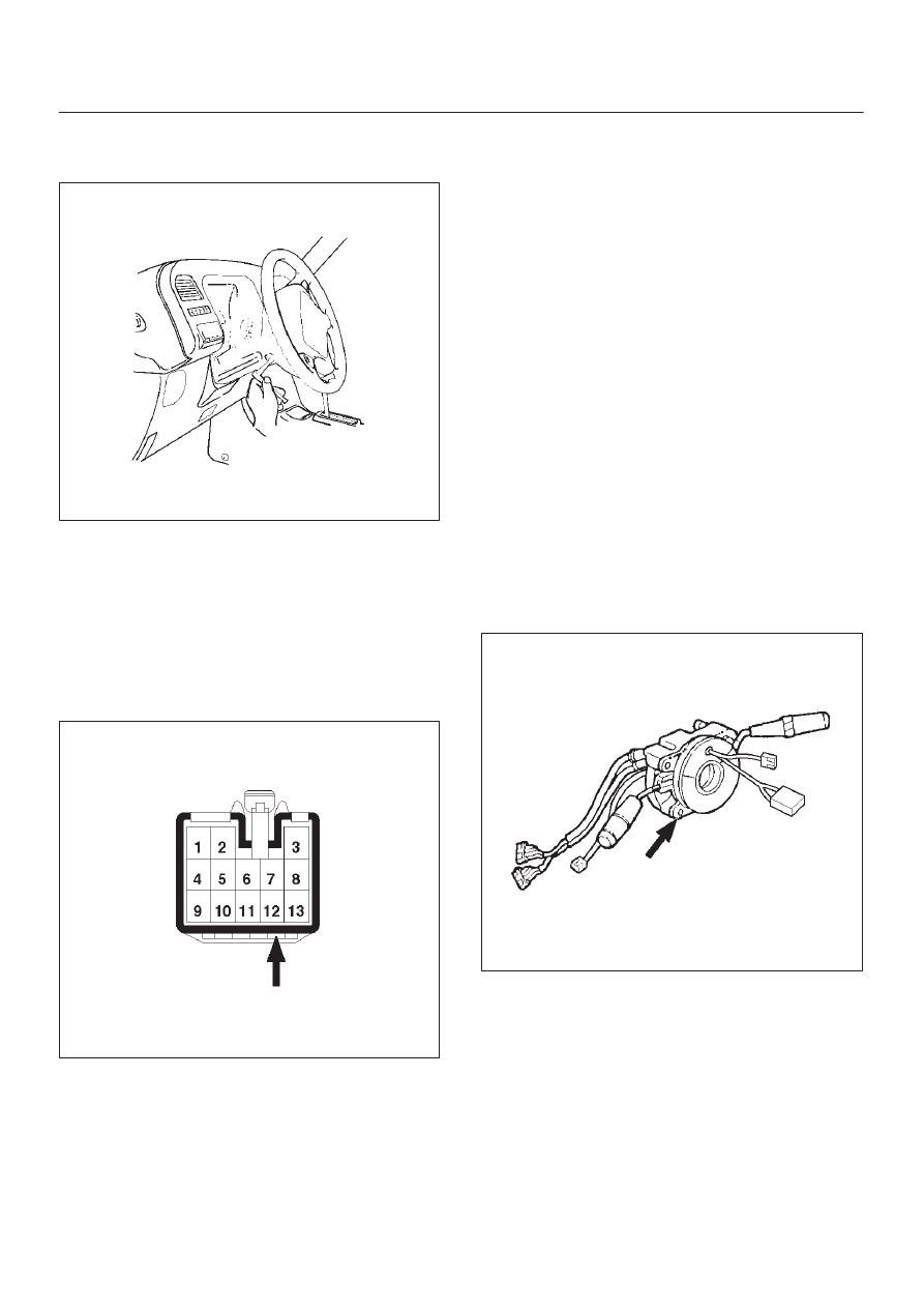
2. Disconnect the horn terminal NO.12 from connector

and remove the tape binding harness. (Refer to How
to Disconnect the horn terminal in this section.)

827RX029

3. Remove four bolts of SRS coil assembly and remove

the SRS coil assembly from the combination switch.

825RX033

SUPPLEMENTAL RESTRAINT SYSTEM

9J–43

How to Disconnect the horn terminal

1. Lift the terminal lock plate from upper portion of

connector with a minitenes screw driver (-) and
release connector terminal lock.

827RX045

Legend

(1) Minitenes screw driver (-)
(2) Connector lock knob

2. Pull out the terminal of lead wire coming to connector

NO.12 while lifting the lock part with a minitenes
screw driver (-).

827RX046

Legend

(1) Lock
(2) Minitenes screw driver (-)
(3) Terminal

How to Connect Horn Terminal

1. Insert horn terminal from behind black connector

NO.12 until connector lock works.

827RX047

Legend

(1) Terminal
(2) Connector lock knob

2. Push terminal lock plate into the connector for a duble

lock.

827RX048

SUPPLEMENTAL RESTRAINT SYSTEM

9J–44

Installation

1. Set cancel cam and SRS coil in position and install the

SRS coil to combination switch by tightening the four
bolts to a specified tightening torque with four bolts.

Torque: 0.5 N·m (0.05 kg·m/4 Ib ft)

825RX033

2. Insert the horn terminal into the connector NO.12 and

bind the combination switch harness and SRS coil
harness with a tape. (Refer to How to Connect the
Horn Terminal in this section.)

3. After installation steps above, same steps as SRS

Coil Assembly installation step 2 to step 13.

Steering Column

Service Precautions

WARNING: SAFETY PRECAUTIONS MUST BE
FOLLOWED WHEN HANDLING A DEPLOYED AIR
BAG ASSEMBLY. AFTER DEPLOYMENT, THE AIR
BAG ASSEMBLY SURFACE MAY CONTAIN A SMALL
AMOUNT OF SODIUM HYDROXIDE, A BY–PRODUCT
OF THE DEPLOYMENT REACTION, THAT IS
IRRITATING TO THE SKIN AND EYES. MOST OF THE
POWER ON THE AIR BAG ASSEMBLY IS
HARMLESS. AS A PRECAUTION, WEAR GLOVES
AND SAFETY GLASSES WHEN HANDLING A
DEPLOYED AIR BAG ASSEMBLY, AND WASH YOUR
HANDS WITH MILD SOAP AND WATER
AFTERWARDS.

WARNING: WHEN CARRYING A LIVE AIR BAG
ASSEMBLY, MAKE SURE THE BAG AND TRIM
COVER ARE POINTED AWAY FROM YOU. NEVER
CARRY AIR BAG ASSEMBLY BY THE WIRES OR
CONNECTOR ON THE UNDERSIDE OF MODULE. IN
THE CASE OF AN ACCIDENTAL DEPLOYMENT, THE
BAG WILL THEN DEPLOY WITH MINIMAL CHANCE
OF INJURY. WHEN PLACING ALIVE AIR BAG
ASSEMBLY ON A BENCH OR OTHER SURFACE,
ALWAYS FACE BAG AND RIM COVER UP, AWAY
FROM THE SURFACE. NEVER REST A STEERING
COLUMN ASSEMBLY ON THE STEERING WHEEL
WITH THE AIR BAG ASSEMBLY FACE DOWN AND
COLUMN VERTICAL. THIS IS NECESSARY SO THAT
A FREE SPACE IS PROVIDED TO ALLOW THE AIR
BAG ASSEMBLY TO EXPAND IN THE UNLIKELY
EVENT OF ACCIDENTAL DEPLOYMENT.
OTHERWISE, PERSONAL INJURY COULD RESULT.

NOTE: In the event deployment has occurred, inspect
coil assembly wire for any signs of scorching, melting or
any other damage due to excessive heat. If the coil has
been damaged, replace it.

Removal

1. Disable the SRS (Refer to “Disabling the SRS ” in this

section).

2. Loosen the air bag assembly fixing bolts from behind

the steering wheel assembly using a TORX

 driver or

equivalent until the air bag assembly can be released
from steering wheel.

827RT008

SUPPLEMENTAL RESTRAINT SYSTEM

9J–45

3. Disconnect the yellow 2–pin connector located

behind the air bag assembly and remove air bag
assembly.Refer to “SRS Connectors” in this section
for removal and installation.

827RT009

4. Disconnect horn lead connector.
5. Remove the steering wheel attachment nut.
6. Apply a setting mark across the steering wheel and

shaft so parts can be  reassembled in their original
position.

430RS004

7. Move the tires to the straight ahead position before

removing the steering wheel and removing wheel with
5–8521–0016–0.

430RT009

8. Feed wiring though the wheel and remove  wheel.
9. Remove the steering lower cover and engine hood

opening lever.

10. Remove the driver knee bolster assembly.

740RT015

11. Remove the steering column cover.

12. Remove air conditioning lower duct.
13. Disconnect the wiring harness connectors located at

the base of steering column.

CAUTION: Never apply force to the steering wheel
in direction of the shaft by using a hammer or other
impact tools in an attempt to remove the steering
wheel. The steering shaft is designed as an energy
absorbing unit.

14. Remove the combination switch assembly  with SRS

coil.


Content   ..  1801  1802  1803  1804   ..