Opel Frontera UBS. Manual - part 1772


  Index      Opel     Opel Frontera UBS - service repair manual 1998-2002 year


Search            


Content   ..  1770  1771  1772  1773   ..


Opel Frontera UBS. Manual - part 1772


SECURITY AND LOCKS

8H–17

Tailgate Outside Handle and/or Tailgate Lock Cylinder

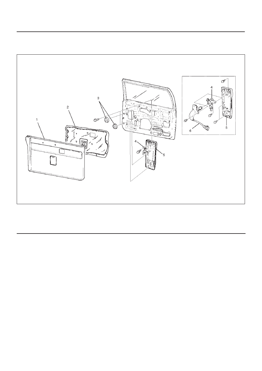
Tailgate Outside Handle and/or Tailgate Lock Cylinder and Associated Parts

684RW007

Legend

(1) Tailgate Trim Panel (LH)
(2) Waterproof Sheet
(3) Grommet

(4) Tailgate Lock Cylinder
(5) Tailgate Outside Handle
(6) Key Switch (W/Anti–Theft)

Removal

1. Disconnect the battery ground cable.
2. Remove the tailgate trim panel.
3. Remove the waterproof sheet.

D

Refer to the Tailgate Lock Assembly (LH) in this
section.

4. Remove the grommet.

8H–18 SECURITY AND LOCKS

5. Disconnect the locking links (arrow marks positions),

key switch connector (w/anti-theft) and remove three
fixing bolts to remove the tailgate outside handle.

683RW016

Legend

(1) To Actuator
(2) Key Switch Connector (W/Anti–Theft)
(3) To Lock Assembly

6. Remove the key switch fixing bolt(3) to remove the

key switch (w/anti-theft) (4) from the tailgate lock
cylinder (1).
And remove the tailgate lock cylinder fixing bolt(2) to
remove the tailgate lock cylinder.

683RS008

Installation

To install, follow the removal steps in the reverse order,
noting the following points.

1. For the anti-theft system, install the push rod(1) of the

key switch(3) to the key cylinder(2) while pressing it
so that there is not continuity between the key switch
side connector terminals No. G5–2 and G5–4 as
shown in the figure.

683RS009

2. Tighten the outside handle and key cylinder fixing

bolts to the specified torque.

Torque: 9 N·m (0.9kg·m/78 lb in)

3. Check that the outside handle and key cylinder

operate correctly after installing them.

SECURITY AND LOCKS

8H–19

Key

Key Coding

730RY00001

Legend

(1) Key(Actual Size)
(2) Key Code Tag

(3) Position
(4) Level

One key is used for the ignition, door, and tailgate lock
cylinders. The keys are cut on both edges to make them
reversible.
Key identification is obtained from the five character key
code stamped on the key code tag.  From this key code,
the key code cutting combination can be determined from
a code list (available to owners of key cutting equipment
from suppliers).
If key codes are not available from records or tags, the
key code can be obtained from the right hand door lock
cylinder (if lock has not been replaced).  Lock cylinders
supplied by the factory as service parts are unmarked.
If the original key is available, the key code cutting
combination can be determined by laying the key on the
diagram shown in the figure.

Key Styles

730RY00001

Legend

(1) Blank Key Style “A”
(2) Blank Key Style “B”

The keys come in styles A or B depending on the key code
cutting combination.  When the first position in the
combination is a 1, 2 or 3, Style A is used.  When the first
position is a 4, Style B (factory pre-cut key) is used.

8H–20 SECURITY AND LOCKS

Power Door Lock System

General Description

The circuit consists of the door lock (& power window)
switch, door lock actuator for the front and rear door,
tailgate lock actuator and the door lock key switch.  The
front door lock switch –LH is always provided with battery
voltage.
The key or the inside lock button on the both driver’s and
the front passenger’s door can activate the lock
mechanism of all the doors (including the tailgate).
When the driver’s door lock switch or the front
passenger’s door lock switch is turned on, current flows
for about one second to the door lock actuator of each
door connected in parallel with the front door lock (&
power window) switch –LH to activate the actuator to lock
and unlock the doors.

Front Door Lock Actuator Removal

1. Refer to the Front Door Lock Assembly removal

procedure in this section.

2. Remove the door lock actuator(1).

632RS021

632RS020

Front Door Lock Actuator Installation

To install, follow the removal steps in the reverse order.

Rear Door Lock Actuator Removal

1. Refer to the Rear Door Lock Assembly removal

procedure in this section.

2. Removal the door lock actuator(1).

632RS019


Content   ..  1770  1771  1772  1773   ..