Content .. 1715 1716 1717 1718 ..
Opel Frontera UBS. Manual - part 1717
8D–546
WIRING SYSTEM
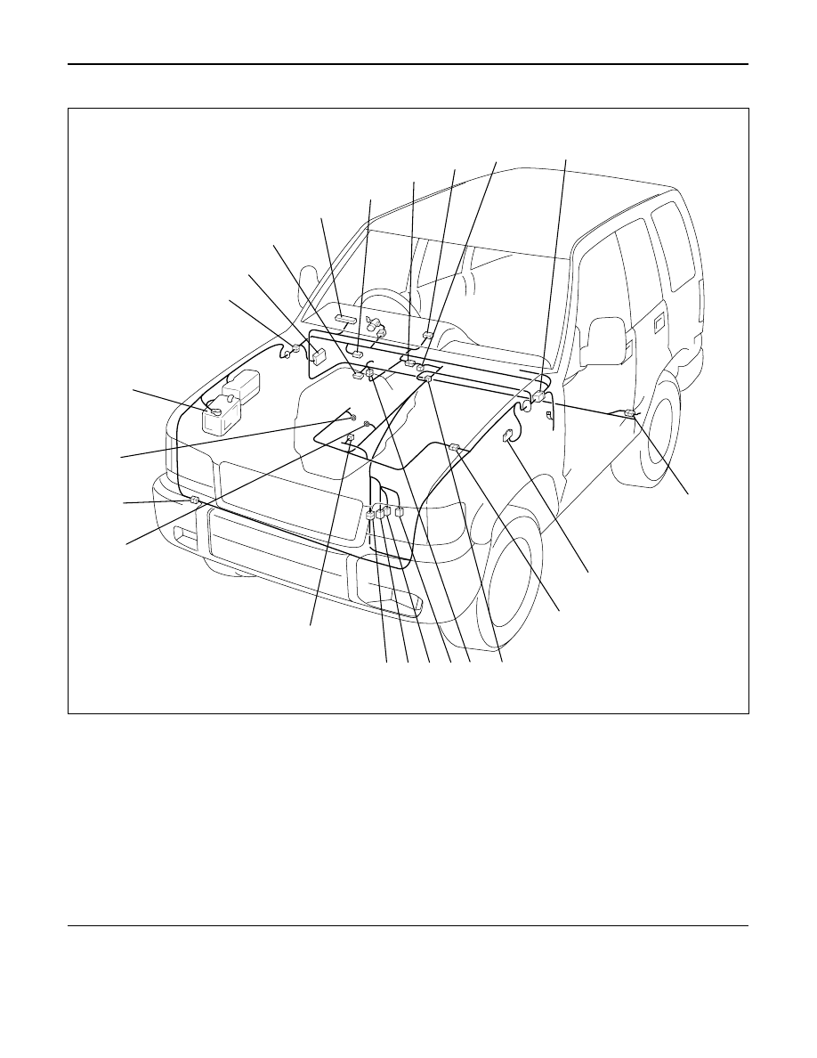
Parts Location
Legend
(1) I-9
(2) B-13 or B-14
(3) H-12
(4) I-12
(5) A-3
(6) H-7, H-8
(7) H-32
(8) C-16
(9) H-5, H-6
(10) C-63
(11) H-49
(12) M-22
(13) M-23
(14) M-24
(15) H-10
(16) E-5
(17) E-29
(18) H-42
(19) E-30
(20) Battery
(21) H-13, H-15, H-26
(22) Fuse Box
(23) B-67, B-68
D08RW621
1
2
3
4
5
8
7
9
10
11
12
13
14
15
16
17
18
19
20
21
22
23
6