Content .. 1609 1610 1611 1612 ..
Opel Frontera UBS. Manual - part 1611
8D–122
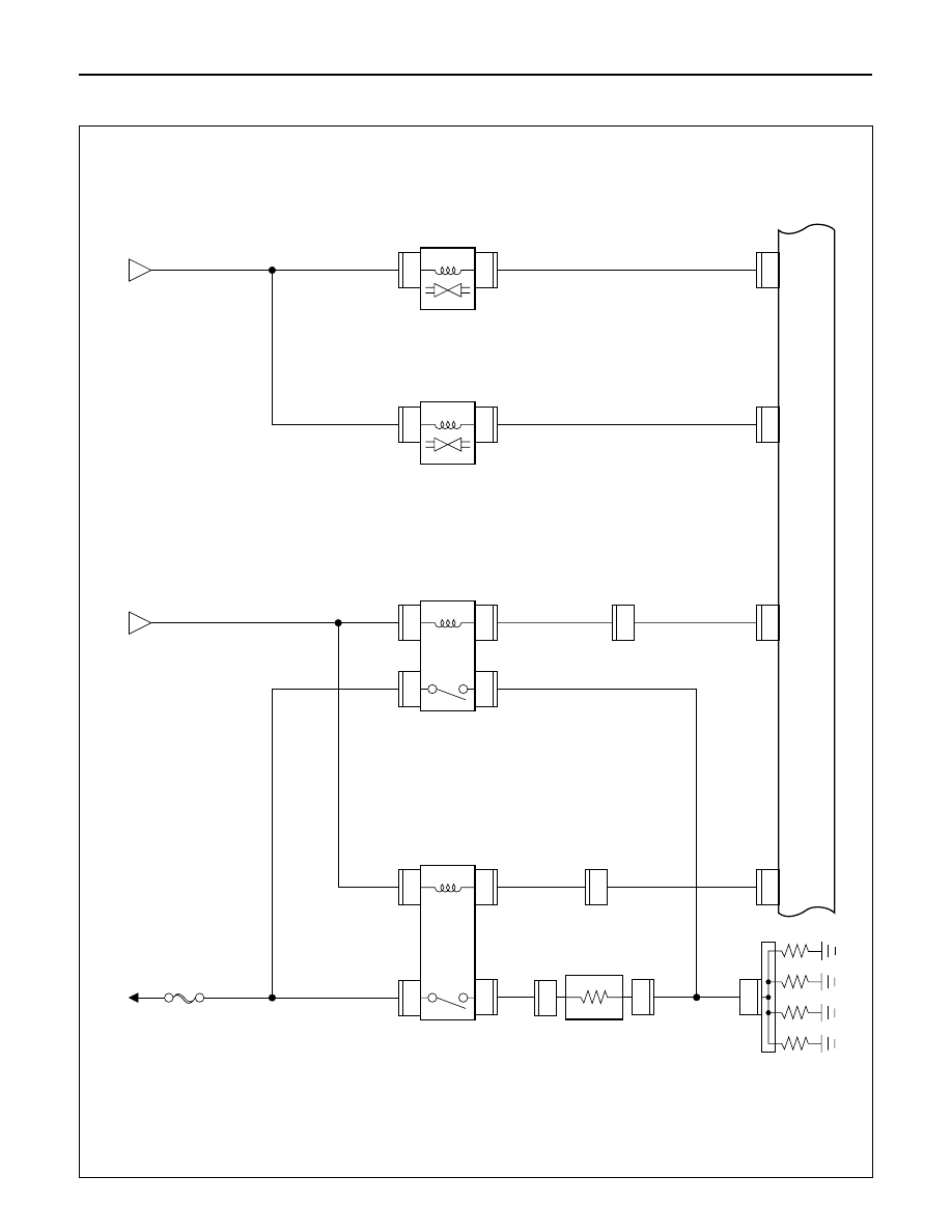
WIRING SYSTEM
DROPPING
RESIST
OR
GLOW
PLUG
GLOW
RELA
Y
-2
QOS/EGR CONTROL
UNIT
GLOW
RELA
Y
-1
C-66
6
H-42
16
1
1
C-60
C-59
3.0
R/W
3.0
B/Y
3.0
B/R
0.5
B/G
0.5
B/G
0.85
B/Y
FL-5 50A
GLOW
C-53
1
C-59
2
1
C-54
BA
TT
.(+)
C-55
1
2
C-55
A
C-66
7
H-41
7
3.0
B/R
0.5
B/L
0.5
B/L
0.85
B/Y
0.85
B/Y
3.0
R/W
C-51
1
C-51
C-52
1
2
2
C-52
VSV
;
EVR
V
B
C-66
10
0.5
R
0.85
B/Y
0.85
B/Y
C-72
1
2
C-72
VSV
;
EGR
C-66
4
0.5
G
0.85
B/Y
C-73
1
2
C-73
D08RW985
Circuit Diagram (LHD)-2