Content .. 1582 1583 1584 1585 ..
Opel Frontera UBS. Manual - part 1584
8D–14
WIRING SYSTEM
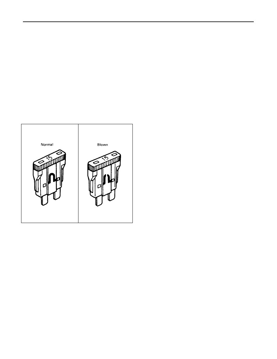
Fuse
Fuses are the most common form of circuit protection
used in vehicle wiring. A fuse is a thin piece of wire or strip
of metal encased in a glass or plastic housing. It is wired
in series with the circuit it protects. When there is an
overload of current in a circuit, such as a short of a ground,
the metal strip is designed to burn out and interrupt the
flow of current. This prevents a surge of high current from
reaching and damaging other components in the circuit.
Determine the cause of the overloaded before replacing
the fuse.
The replacement fuse must have the same amperage
specification as the original fuse.
Never replace a blown fuse with a fuse of a different
amperage specification.
Doing so can result in an electrical fire or other serious
circuit damage. A blown fuse is easily identified as shown
in the figure.