Opel Frontera UBS. Manual - part 1573


  Index      Opel     Opel Frontera UBS - service repair manual 1998-2002 year


Search            


Content   ..  1571  1572  1573  1574   ..


Opel Frontera UBS. Manual - part 1573


8A–24

LIGHTING SYSTEM

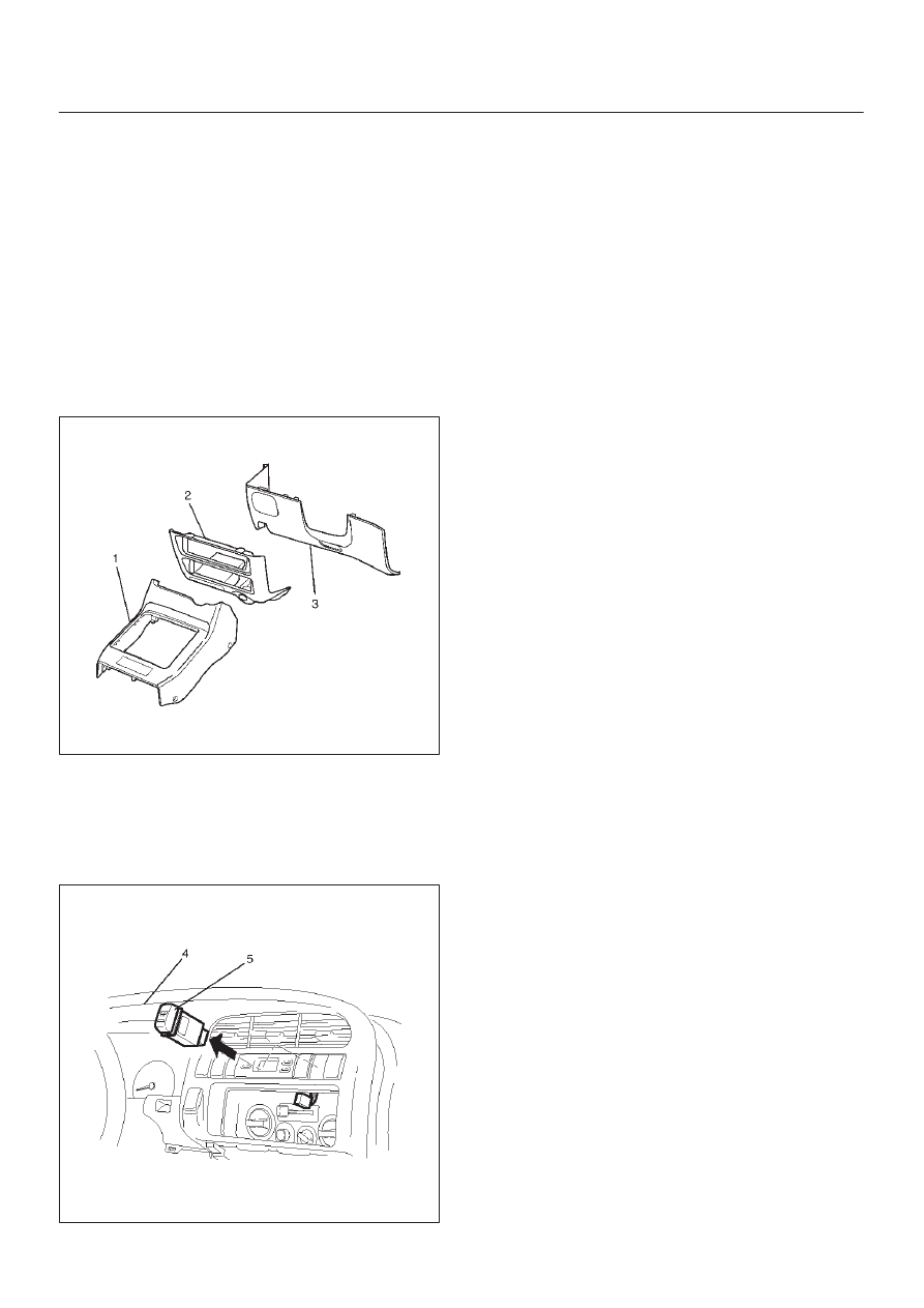
Rear Defogger Switch

Removal

1. Disconnect the battery ground cable.
2. Remove the front console assembly(1). 

Refer to the Instrument Panel Assembly in Body
Structure section.

3. Remove the lower cluster assembly(2). 

Refer to the Instrument Panel Assembly in Body
Structure section.

4. Remove the instrument panel driver lower cover

assembly(3). 
Refer to the Instrument Panel Assembly in Body
Structure section.

821RW024

5. Remove the instrument panel cluster assembly(4). 

Refer to the Instrument Panel Assembly in Body
Structure section.

6. Disconnect the connector and push the lock from the

back side of the instrument panel cluster assembly to
remove the rear defogger switch(5). 

825RW023

Installation 

To install, follow the removal steps in the reverse order,
noting the following point.

1. Push in the switch with your fingers until it locks

securely. 

LIGHTING SYSTEM

8A–25

Seat Heater Switch

Removal 

1. Disconnect the battery ground cable. 
2. Remove four fixing screws and disconnect the switch

connectors to remove the front console assembly(4). 

3. Push the lock from the back side of the front console

assembly to remove the seat heater switch(5). 

825RW025

Installation

To install, follow the removal steps in the reverse order,
noting the following point.

1. Push the switch with your fingers until it locks

securely. 

Key Remind Switch (Starter Switch)

Removal and Installation

Refer to the removal and installation on steps of the
Starter Switch in this section.

8A–26

LIGHTING SYSTEM

Illumination Controller

Removal

1. Disconnect the battery ground cable. 
2. Remove the front console assembly(1). 

Refer to the Instrument Panel Assembly in Body
Structure section.

3. Remove the lower cluster assembly(2). 

Refer to the Instrument Panel Assembly in Body
Structure section.

4. Remove the instrument panel driver lower cover

assembly(3). 
Refer to the Instrument Panel Assembly in Body
Structure section.

821RW024

5. Remove the instrument panel cluster assembly(4). 

Refer to the Instrument Panel Assembly in Body
Structure section.

6. Disconnect the connector and push the lock from the

back side of the instrument panel cluster assembly to
remove the illumination controller(5). 

825RW026

Installation 

To install, follow the removal steps in the reverse order,
noting the following point.

1. Push in the switch with your fingers until the switch is

locked securely. 

LIGHTING SYSTEM

8A–27

Power/Winter Switch

Removal

1. Disconnect the battery ground cable. 
2. Remove four fixing screws and disconnect the switch

connectors to remove the front console assembly(4).

3. Push the lock from the back side of the front console

assembly to remove the power/winter switch(5).

825RW204

Installation 

To install, follow the removal steps in the reverse order,
noting the following point.

1. Push the switch with your fingers until it locks

securely.


Content   ..  1571  1572  1573  1574   ..