Opel Frontera UBS. Manual - part 154


  Index      Opel     Opel Frontera UBS - service repair manual 1998-2002 year


Search            


Content   ..  152  153  154  155   ..


Opel Frontera UBS. Manual - part 154


DRIVE LINE CONTROL SYSTEM (TOD)

4B2–68

Chart C–2

The 4H switch circuit is short-circuited to GND.
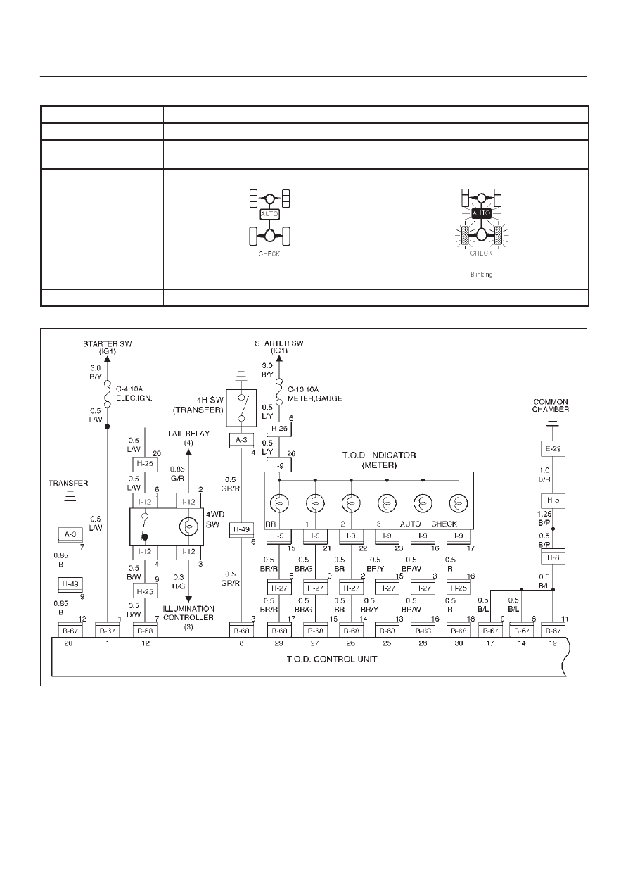
Function of circuit

Fail condition

When the transfer lever is shifted to 4L, the indicator lamp status is not changed.

When the transfer lever is shifted to High, the indicator lamp blinks at TOD mode.

Indicator lamp status

Transfer position

4L

High (TOD)

D04RW062

4B2–69

DRIVE LINE CONTROL SYSTEM (TOD)

Step

Action

Yes

No

1

When the transfer lever is shifted to the High position, is 5V
observed between terminals 8 and 19 (4H switch)?

Go to Step 2

Go to Step 14

2

When the transfer lever is shifted to the neutral position, is 0V
observed between terminals 8 and 19 (4H switch)?

Go to Step 3

Go to Step 14

3

When the transfer lever is shifted to the 4L position, is 5V
observed between terminals 8 and 19 (4H switch)?

Go to Step 4

Go to Step 14

4

1. Turn off the starter switch.

Is the continuity established between terminals 1 and 25?

Go to Step 5

Replace TOD
indcator lamp

bulb.

Go to Step 23

5

Is the continuity established between terminals 1 and 26?

Go to Step 6

Replace TOD

indicator lamp

bulb.

Go to Step 23

6

Is the continuity established between terminals 1 and 27?

Go to Step 7

Replace TOD

indicator lamp

bulb.

Go to Step 23

7

Is the continuity established between terminals 1 and 28?

Go to Step 8

Replace TOD

indicator lamp

bulb.

Go to Step 23

8

Is the continuity established between terminals 1 and 29?

Go to Step 9

Replace TOD

indicator lamp

bulb.

Go to Step 23

9

1. Turn on the starter switch.
2. Shift the transfer lever is shifted to the 4L position.

Is 0 V observed between terminals 25 and 20?

Go to Step 10

The ECU has

failed.  Replace

the ECU.

Go to Step 23

10

Is 0 V observed between terminals 26 and 20?

Go to Step 11

The ECU has

failed.  Replace

the ECU.

Go to Step 23

11

Is 0 V observed between terminals 27 and 20?

Go to Step 12

The ECU has

failed.  Replace

the ECU.

Go to Step 23

12

Is 12 V observed between terminals 28 and 20?

Go to Step 13

The ECU has

failed.  Replace

the ECU.

Go to Step 23

13

Is 0 V observed between terminals 29 and 20?

The phenomenon

is not

reproduced.

Refer to

“Troubles

intermittently

observed”.

Go to Step 23

The ECU has

failed.  Replace

the ECU.

Go to Step 23

DRIVE LINE CONTROL SYSTEM (TOD)

4B2–70

Step

No

Yes

Action

14

1. Turn off the starter switch.
2. Disconnect the ECU connector.

When the transfer lever is shifted to the neutral position, is the
continuity established between terminals (B–68)3 and (B–67)11
(4H switch)?

Go to Step 15

Go to Step 17

15

When the transfer lever is shifted to the high position, is the
continuity established between terminals (B–68)3 and (B–67)11?

Go to Step 17

Go to Step 16

16

When the transfer lever is shifted to the 4L position, is the
continuity established between terminals (B–68)3 and (B–67)11?

The ECU has

failed. Replace

the ECU.

Go to Step 23

Go to Step 17

17

1. Disconnect the H–49 connector.

When the transfer lever is shifted to the neutral position between
high and 4L, is the continuity established between terminals
(H-49)6 and (B-68)3?

Go to Step 18

Go to Step 20

18

When the transfer lever is shifted to the high position, is the
continuity established between transfer connector terminals
(H-49)6 and (B-68)3?

Go to Step 20

Go to Step 19

19

When the transfer lever is shifted to the 4L position, is the
continuity established between transfer connector terminals
(H-49)6 and (B-68)3?

Go to Step 20

GND is

short-circuited

between

terminals (B-68)3

and (H-49)6.

Repair the circuit.

Go to Step 23

20

1. Disconnect the A–3 connector.

When the transfer lever is shifted to the neutral position between
high and 4L, is the continuity established between terminals
(A-3)4 and (B-68)3?

Go to Step 21

Repair the

transfer

assembly.

Go to Step 23

21

When the transfer lever is shifted to the high position, is the
continuity established between terminals (A-3)4 and (B-68)3?

Repair the

transfer

assembly.

Go to Step 23

Go to Step 22

22

When the transfer lever is shifted to the 4L position, is the
continuity established between terminals (A-3)4 and (B-68)3?

Repair the

transfer

assembly.

Go to Step 23

GND is

short-circuited

between

terminals (B-68)3

and (A–3)4.

Repair the circuit.

Go to Step 23

23

Check that all the parts are mounted.

Is this step complete?

Repeat the

“Diagnosis Flow”.

Return to Step 23

4B2–71

DRIVE LINE CONTROL SYSTEM (TOD)

Chart D–1

4L switch circuit wires are broken or the battery is short-circuited.

Function of circuit

Fail condition

The TOD mode is displayed in the neutral position between high and 4L. When the lever

is shifted to the 4L position, the TOD mode is displayed.

Indicator lamp status

Transfer position

4L

Neutral

D04RW061


Content   ..  152  153  154  155   ..