Content .. 1505 1506 1507 1508 ..
Opel Frontera UBS. Manual - part 1507
7A1–58 TRANSMISSION CONTROL SYSTEM (4L30–E)
DTC P0753 Shift Solenoid A Electrical
D07RW009
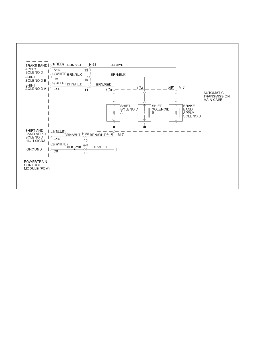
Circuit Description
D
The shift solenoid A is a simple on/off solenoid
located in the main case valve body. The solenoid is
the normally closed type. In second or third gear, the
Powertrain Control Module (PCM) energizes the
solenoid to open a fluid inlet port. When the port is
open, fluid pressure actuates the shift valve.
D
The solenoid is activated by current. This current is
produced by applying a voltage to one side (the High
side) and a ground to the other side (Low side).
D
The High Side Driver (HSD) is a circuit of the PCM
that acts as a switch between the solenoids and the
supply voltage. The High side of the solenoid is
permanently supplied with voltage, except in
BACKUP MODE or when ignition is off the HSD is
turned off.
This DTC detects a continuous open or short to ground in
the shift solenoid A circuit or the shift solenoid A. This is a
type “C” DTC.
Conditions For Setting The DTC
D
Ignition is “on”, Engine “run”.
D
Battery voltage is between 10 and 16 volts.
D
The PCM commands the solenoid “on” and the
voltage remains high (B+) or the PCM commands the
solenoid “off” and the voltage remains low (zero
volts).
D
All conditions met for 0.33 seconds.
Action Taken When The DTC Sets
D
Maximum line pressure.
D
Immediate landing to 4th gear.
D
Inhibit TCC engagement.
D
The PCM will illuminate the CHECK TRANS Lamp.
Conditions For Clearing The DTC/CHECK
TRANS Lamp
D
The PCM will turn off the CHECK TRANS Lamp after
three consecutive ignition cycles without a failure
reported.
D
The DTC can be cleared from the PCM history by
using a scan tool.
D
The DTC will be cleared from history when the vehicle
has achieved 40 warmup cycles without a failure
reported.
D
The PCM will cancel the DTC default actions when
the fault no longer exists and the ignition is cycled “off”
long enough to power down the PCM.
Diagnostic Aids
D
Inspect the wiring for poor electrical connection at the
PCM and at the transmission 16–way connector.
Look for possible bent, backed out, deformed or
damaged terminals. Check for weak terminal tension
as well. Also check for a chafed wire that could short
to bare metal or other wiring. Inspect for a broken wire
inside the insulation.