Content .. 1450 1451 1452 1453 ..
Opel Frontera UBS. Manual - part 1452
7A–50
AUTOMATIC TRANSMISSION (AW30-40LE)
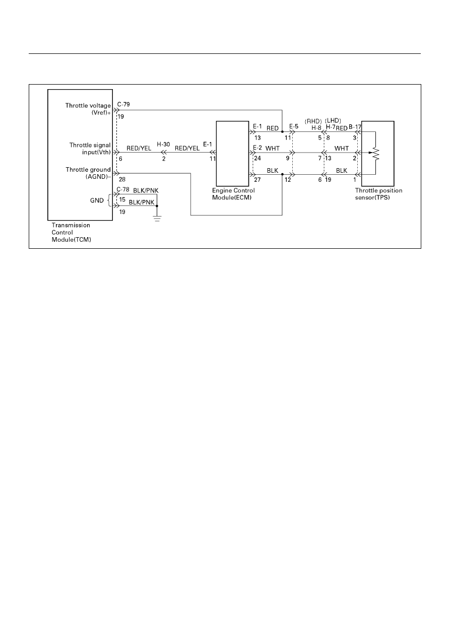
DTC P1121 (FLASHING CODE 23) ANALOG THROTTLE SIGNAL FAILURE (VREF, VGND)
D07RY00023
Circuit description:
When the signal of the engine throttle position sensor
located on the accelerator pedal is supplied to the
transmission TCM, the TCM judges the opening
condition of the throttle.
The shift point of the transmission is determined by this
opening condition of the throttle.
Fail-safe control:
The TCM controls fail-safe by detecting analog throttle
signal (VREF, VGND) failure.
Failure detection:
• When the Vref input voltage is detected more than
5.55V or less than 4.45V.
• When the Vgnd input voltage is detected more than
0.40V or less than -0.40V.
• When the failure criteria is continuously for 1.0 sec.
Contents of control:
At failure detection
• Judges throttle opening of linear sensor (Vth) as
Vref:5V, Vgnd:0V
• Throttle learning control inhibit
• Up hill and down hill control inhibit
At failure decision
Executes following items in addition to above control
items at failure detection.
• Stores the failure information in failure-memory
Conditions of turning “CHECK TRANS” lamp off:
None
Reversion conditions from fail-safe:
At failure detection
When the Vref input voltage is detected less than 5.55 V
and more than 4.45 V.
When the Vgnd input voltage is detected less than 0.40 V
and more than -0.40 V.
At failure decision
• Recovers when judged 0km/h by output revolution
sensor after the Vref input voltage is detected less
than 5.55V and more than 4.45V.
(however, uses 0 km/h judgment by back-up vehicle
speed at output revolution failure)
• Recovers when judged 0km/h by output revolution
sensor after the Vgnd input voltage is detected less
than 0.40V and more than -0.40V.
(however, uses 0 km/h judgment by back-up vehicle
speed at output revolution failure)
Test description:
The following numbers correspond to circled numbers on
the diagnostic chart.
(1) Check the power supply voltage (4.75-5.25V) of
throttle position sensor.
Diagnostic aids:
An intermittent may be caused by a poor connection,
rubbed through wire insulation or a wire broken inside
the insulation. Inspect related harness connector for
backed out terminals, improper mating, broken locks,
improperly formed or damaged terminals, poor terminal
to wire connection and damaged harness.