Opel Frontera UBS. Manual - part 144


  Index      Opel     Opel Frontera UBS - service repair manual 1998-2002 year


Search            


Content   ..  142  143  144  145   ..


Opel Frontera UBS. Manual - part 144


DRIVE LINE CONTROL SYSTEM (TOD)

4B2–28

Getting Started

D

Before operating the Isuzu PCMCIA card with the
Tech 2, the following steps must be performed:

1. The Isuzu 98 System PCMCIA card (1) inserts into

the Tech 2 (5).

2. Connect the SAE 16/19 adapter (3) to the DLC cable

(4).

3. Connect the DLC cable to the Tech 2 (5)
4. Mark sure the vehicle ignition is off.
5. Connect the Tech 2 SAE 16/19 adapter to the vehicle

ALDL/DLC connector.

810RW308

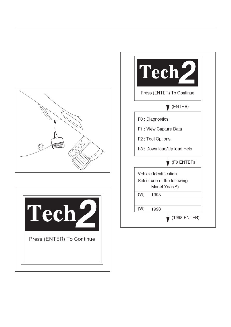
6. The vehicle ignition turns on.
7. Verify the Tech 2 power up display.

060RW009

NOTE: The RS232 Loop back connector is only to use for
diagnosis of Tech 2 and refer to user guide of the Tech 2.

Operating Procedure

The power up screen is displayed when you power up the
tester with the Isuzu systems PCMCIA card. Follow the
operating procedure below.

060RW014

4B2–29

DRIVE LINE CONTROL SYSTEM (TOD)

D04RW029

DRIVE LINE CONTROL SYSTEM (TOD)

4B2–30

Diagnostic Trouble Codes

Code

Item

Diagnosis

Check flow No.

12

Start code

Normal

13

Ref

Shorted GND

6

14

Front speed sensor

Input abnormality (open, sig or com)

2

15

Ref

Shorted V

B

6

16

Front speed sensor

Input abnormality

3

21

TPS

Shorted or disconnected wiring, abnormality in
input

7

23

ECU

CPU abnormality

1

24

Rear speed sensor

Input abnormality (open, sig or com)

5

25

CHECK lamp

Shorted

14

26

EMC (+)

Shorted GND

10

27

Rear speed sensor

Input abnormality

4

28

ADC (+) & AXLE SW

Output abnormality

11

31

EMC (+)

Shorted or disconnected coil/wiring

9

32

ADC (+)

Shorted or disconnected coil/wiring

12

33

ADC (+)

Shorted GND

13

34

D-G MAP

Input abnormality

8

35

CHECK lamp

Shorted or disconnected wiring

14

36

ECU

CPU abnormality

1

37

ECU

CPU abnormality

1

38

ECU

CPU abnormality

1

TPS : Throttle Position Sensor
EMC : Electromagnetic coil
ADC : Shift on the fly (Axle Dis Connect)
D-G MAP : Discrimination engine type

4B2–31

DRIVE LINE CONTROL SYSTEM (TOD)

Diagnosis from Trouble Codes

D

Diagnose the TOD based on the fault that has been
saved to the control unit according to the system
self-diagnostic function.

Check flow

Trouble code

Phenomenon

Standard

1

 23, 36, 37, 38

The ECU is failed.

Step

Action

Yes

No

1

Turn on the starter switch.

Is the trouble reproduced?

Replace the ECU

and conduct the

test run.

Go to Step 3

Go to Step 2

2

1. Clear the trouble codes.
2. Conduct the test run.

Is the trouble reproduced during the test run?

Replace the ECU

and conduct the

test run.

Go to Step 3

The trouble is not

reproduced.

Refer to

“Troubles

intermittently

observed”.

Go to Step 3

3

1. Check that all the parts are mounted.
2. Clear the trouble codes.

Is this step complete?

Repeat the

“Diagnosis Flow”.

Return to Step 3


Content   ..  142  143  144  145   ..