Opel Frontera UBS. Manual - part 1350


  Index      Opel     Opel Frontera UBS - service repair manual 1998-2002 year


Search            


Content   ..  1348  1349  1350  1351   ..


Opel Frontera UBS. Manual - part 1350


6D – 20 ENGINE ELECTRICAL

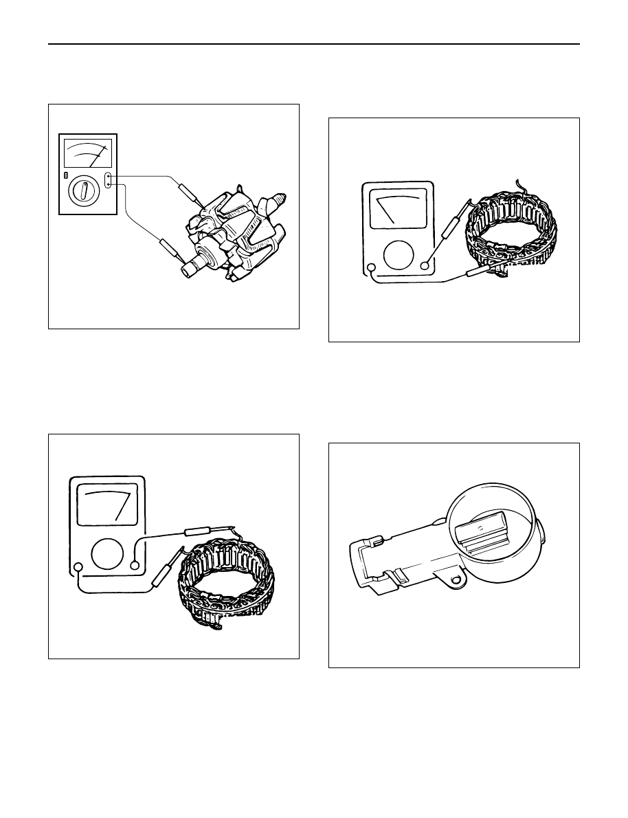
4. Check for continuity between slip ring and rotor

core.
In case of continuity, replace the rotor assembly.

Stator Coil

1. Check for continuity across the stator coils. If no

continuity exists, replace the coils.
Resistance value at 20°C

Standard: Approx 0.07

2. Check for continuity across one of the stator coils

and stator core. If a continuity exists, replace the
coil.

Standard: More than 1M

Brush

Measure the brush length.
If more than limit, replace the brush.

Standard: 18.0 mm (0.709 in)
Limit: 5.5 mm (0.217 in)

+ 

− 

066RS017

066RS035

066RW024

066RS034

ENGINE ELECTRICAL 6D – 21

Rectifier Assembly

1. Measure the resistance between each diode

terminal and aluminum diode fin in forward and
reverse directions with the connection of the tester
leads switched. The diodes are normal if resistance
is nearly zero ohms in one direction and is infinitely
high in the other direction.

2. If a diode has no resistance or equal resistance in

both directions, it is defective and should be
replaced together with the holder.

IC Regulator Assembly

Connect a variable resistor, two 12V batteries, a fixed
resistor, and a voltmeter to the IC regulator as shown in
illustration.
a. Measuring equipment specifications

1. Fixed resistor (R1) : 10 Ohms / 3W
2. Variable resistor (Rv) : 0 – 300 Ohms / 12W
3. Batteries (BAT1, BAT2) : 12V (2 Batteries)
4. DC voltmeter : 0 – 50V / 0.5 steps (4 Check points)

b. Measuring procedure

1. Measure the voltage “V1” across the first battery

(BAT1). If the reading is between 10 and 13 volts,
the battery is normal.

2. Measure the voltage “V3” across both the batteries

(BAT1, BAT2). If the reading is between 20 and 26
bolts, the batteries are normal.

3. Gradually increase the resistance of the variable

resistor from zero. Measure the voltage “V2” (the
voltage across the F and E terminals).
Check to see that the voltage across “V1” changes
at this time. If there is no change, the voltage
regulator is faulty and must be replaced.

4. Measure the voltage at “V4” (the voltage across the

variable resistor center tap and terminal E with the
variable resistor resistance held constant). The
measure voltage should be within the specified
(14.4 ± 0.3 volts) limits. If it is not, the regulator
must be replaced.

Reassembly

To reassemble, follow the disassembly steps in the
reverse order, noting the following points:

NOTE:

1) Never make battery connections with polarities

reversed, or battery will be shorted via the diodes.
This will cause damage to the diodes.

2) Do not connect generator B terminal to ground; it is

connected directly to the battery.
This cable will burn if it is connected to ground.

3) Make sure to disconnect the positive (+) terminal of

the battery when quick-charging battery.
Diodes may be damaged due to abnormal pulse
voltage generated by the quick charger.

4) When reassembling the front section to rear

section, insert a stiff wire into hole in the rear face
of the rear cover from the outboard side to support
the brush in raised position, then insert the front
section to which rotor is assembled.

5) Reassemble parts carefully to be sure they fit into

their original position, paying attention to the
insulated portions.

6) Wipe insulating tubes, washers and plates clean

and install them in position carefully to avoid getting
oil or grease on them.

066RS036

R

E

B

S

R1

RV

BAT2

BAT1

V2

V3

V4

V1

066RW029

6D – 22 ENGINE ELECTRICAL

1. Using a press with a socket wrench attached,

reassemble rotor and rear end cover assembly in
the front cover.

2. Install pulley on the rotor.

Secure the pulley directly in the vise between two
copper plates, and tighten nut to the specified
torque.

Torque: 111 N·m (82 lb ft)

066RS022

066RS010

MAIN DATA AND SPECIFICATIONS

General Specifications

Model

LR160-734B

LR-170-760

Battery voltage

V

12

Rated output

A

60

70

Direction of rotation

Clockwise

(as viewed from pulley side)

Rated rotation speed

rpm

5,000

Maximum speed

rpm

18,000

ENGINE ELECTRICAL 6D – 23

QOS4 PREHEATING SYSTEM

GENERAL DESCRIPTION

QOS4 preheating system features a quick-on glow plug
with thermometer control of the glowing time and the
afterglow time function.

The system consists of the ECM, indicator lamp, ECT
sensor, vehicle speed sensor, relay and temperature
self-control type glow plugs.

With the employment of the ECT sensor, the glow time
changes according to the engine coolant temperature,
thus allowing optimum starting conditions to be
obtained.

The after glow time function is controlled by ECM.

NOTE:
Refer to DTC P0380 and P0381 of 6E section.

SYSTEM DIAGRAM

+

-

KEY
50A

ECM
50A

GLOW
50A

2
WHT/
RED

0.5
BLK/
BLU

ECM

J1-15

3

WHT/

RED

3

RED/

BLK

MAIN
80A

8BLK/RED

Glow
Relay

GLOW PLUG   4

BATT

Heater & A/C

Relay

060RW132


Content   ..  1348  1349  1350  1351   ..