Opel Frontera UBS. Manual - part 1332


  Index      Opel     Opel Frontera UBS - service repair manual 1998-2002 year


Search            


Content   ..  1330  1331  1332  1333   ..


Opel Frontera UBS. Manual - part 1332


6A – 78 ENGINE MECHANICAL

2) Apply liquid gasket (TB1207B or equivalent)

between the cylinder block and the crankcase
fitting surfaces.

3) Install the timing gear case to the cylinder body.
4) Tighten the timing gear case bolt together with

the timing gear case gasket to the specified
torque.

Torque: 20 N·m (2.0 kg·m/14.5 lb·ft)
12. Crankshaft Gear

1) Set key to crankshaft key groove.
2) The timing mark on the crankshaft gear must be

facing outward.

3) Use the crankshaft gear installer to install the

crankshaft gear.
Crankshaft installer: 9-8522-0021-0

Legend

(1) Crankshaft Gear Installer
(2) Crankshaft Gear

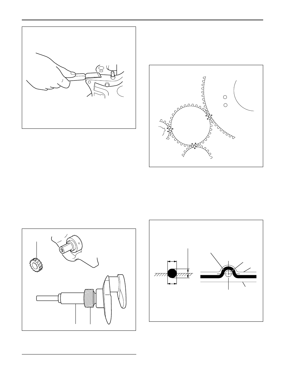
13. Installation of the Timing Gear

1) Align teeth on the scissors gear and lock them

before install timing gear.

2) Align timing marks on each timing gear and

assemble them.

3) Refer to timing gear detail in this manual.

14. Timing Gear Case Cover

1) Remove lock bolt from idle gear A and remove

lock pin from idle gear C.

2) Install oil pump gear oil seal before assembling

timing gear case cover.

3) Clean fitting surface and apply liquid gasket

(TB1207C or equivalent) to fitting surface.

4) Tighten bolts to specified torque.

Torque: 20 N·m (2.0 kg·m/14.5 lb ft)

1

2

2

012RW066

2

2~2.5mm

2~2.5mm

Apply liquid gasket around inside 
of the bolt hole

Bolt hole

Inside

Outside

F06HX00001

012RW024

012RW064

15. Crankshaft Front Oil Seal

1) Set oil seal with special tool.
2) Install front oil seal to timing gear case cover.
Crankshaft Front Oil Seal Installer: 5-8840-2061-0
3) Remove special tool and check oil seal position

from front surface of timing gear case.

Oil Seal Position: 0.5 – 2.5 mm (0.0197 – 0.0984 in)

16. Cylinder Head

1) Refer to “Cylinder head” in this manual.

ENGINE MECHANICAL 6A – 79

015RW074

6A – 80 ENGINE MECHANICAL

PISTON AND CONNECTING ROD

5

8

7

3

1

2

6

4

012RW061

Legend

(1)

Cylinder Head Assembly

(2)

Crank Case

(3)

Connecting Rod Bearing Cap

(4)

Connecting Rod

(5)

Piston Ring

(6)

Piston Pin

(7)

Piston Pin Snap Ring

(8)

Piston

ENGINE MECHANICAL 6A – 81

DISASSEMBLY

1. Cylinder Head Assembly

1) Refer to “Cylinder head” in this manual.

2. Crank Case Assembly

1) Refer to “Crank Case” in this manual.

3. Connecting Rod Bearing Cap
4. Piston and Connecting Rod

1) Remove carbon deposits from the upper portion

of the cylinder wall with a scraper before
removing the piston and connecting rod.

5. Piston Ring

Remove the piston rings with a piston ring
expander.
Arrange the removed piston rings in the cylinder
number order.

6. Piston Pin Snap Ring

1) Use a pair of pliers to remove the piston pin

snap rings.

7. Piston Pin

1) Remove piston pin from piston assembly.

NOTE: Keep the parts removed from each cylinder
separate. All parts must be reinstalled in their original
positions.

8. Piston
9. Connecting Rod

INSPECTION AND REPAIR

PISTON AND PISTON RING

Pistons

Carefully clean away all the carbon adhering to the
piston head and the piston ring grooves.

NOTE: Never use a wire brush to clean the pistons.
Damage will result.  Visually check each piston for
cracking, scoring, and other signs of excessive wear.  If
any of the above conditions are present, the piston
must be replaced.

Piston Diameter

1. Measure the piston outside diameter with

micrometer at the piston grading position.

Piston Grading Position:  69.75 mm (2.7461 in)
from piston head

Piston Outside Diameter

mm(in)

Grade Mark

Outside Diameter

A

95.320 – 95.329 (3.7527 – 3.7531)

B

95.330 – 95.339 (3.7531 – 3.7535)

C

95.340 – 95.349 (3.7535 – 3.7539)

015RW082

015RW077

015LV014


Content   ..  1330  1331  1332  1333   ..