Content .. 1296 1297 1298 1299 ..
Opel Frontera UBS. Manual - part 1298
FUEL SYSTEM 6C – 9
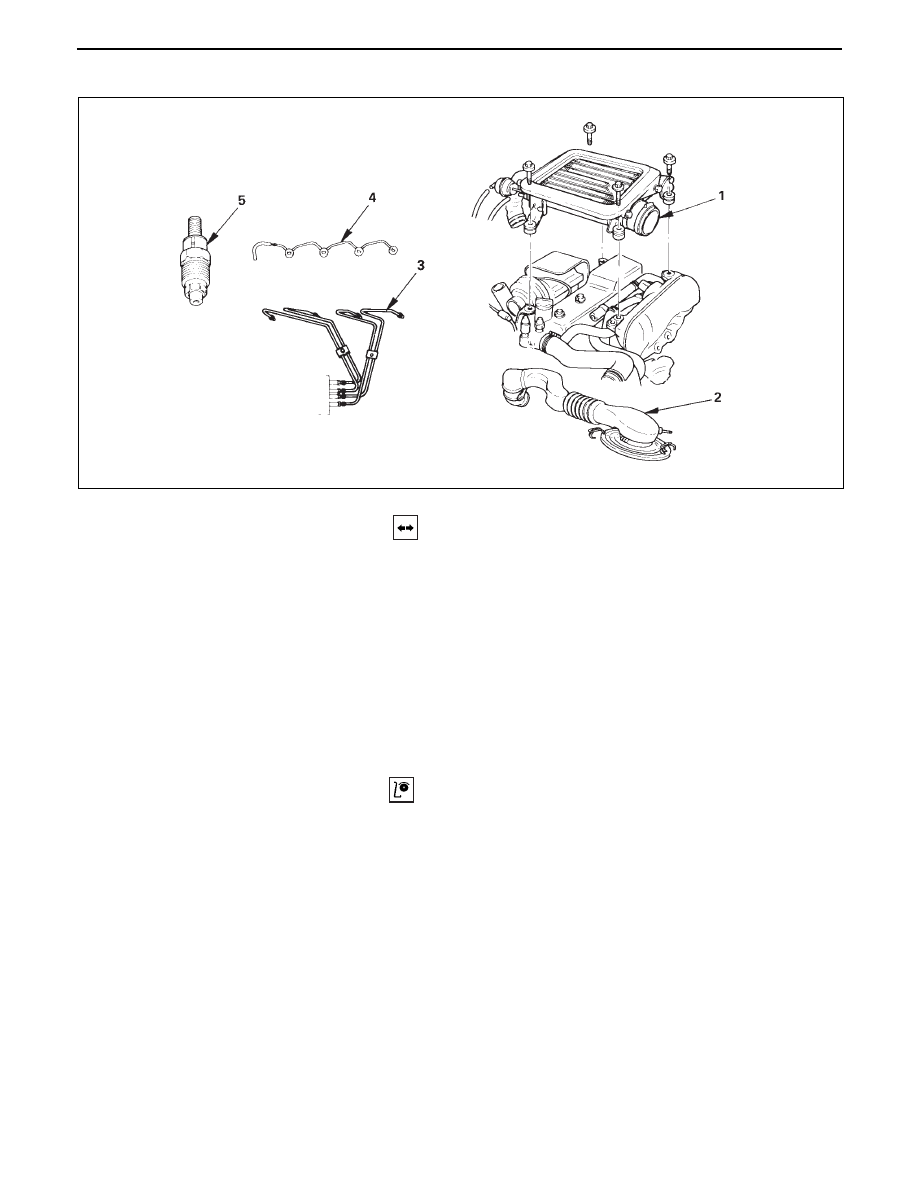
INJECTION NOZZLE
REMOVAL
Preparation:
•
Disconnect battery ground cable.
1.
Intercooler Assembly (4JG2-T Only)
•
(Refer to intercooler removal steps in section 6A2)
2.
Air Cleaner Cover & Air Duct
3.
Injection Pipe
•
Release injection pipe clip.
•
Loosen the flare nut on the injection pump side.
•
Loosen the flare nut on the injection nozzle side,
disconnect and put aside the pipe.
4.
Leak Off Pipe
5.
Injection Nozzle
INSPECTION
•
Set the nozzle in a nozzle tester.
Check there is no fuel leak in the nozzle seal when
a fuel pressure of 14710 kpa (150kg/cm
2
/2133 psi) is
applied.
If there is leak, replace.