Opel Frontera UBS. Manual - part 1234


  Index      Opel     Opel Frontera UBS - service repair manual 1998-2002 year


Search            


Content   ..  1232  1233  1234  1235   ..


Opel Frontera UBS. Manual - part 1234


6E–302

ENGINE DRIVEABILITY AND EMISSIONS

2. Connect the TP electrical connector.
3. Install the negative battery cable.

Vehicle Speed Sensor (VSS)

Removal Procedure

CAUTION: The VSS is located on the right side of
the transfer case just ahead of the rear propeller
shaft and very close to the exhaust pipes.  Be sure
that the exhaust pipes are cool enough to touch
before trying to remove the VSS.  If the pipes are hot,
you could be burned.

1. Disconnect the negative battery cable.
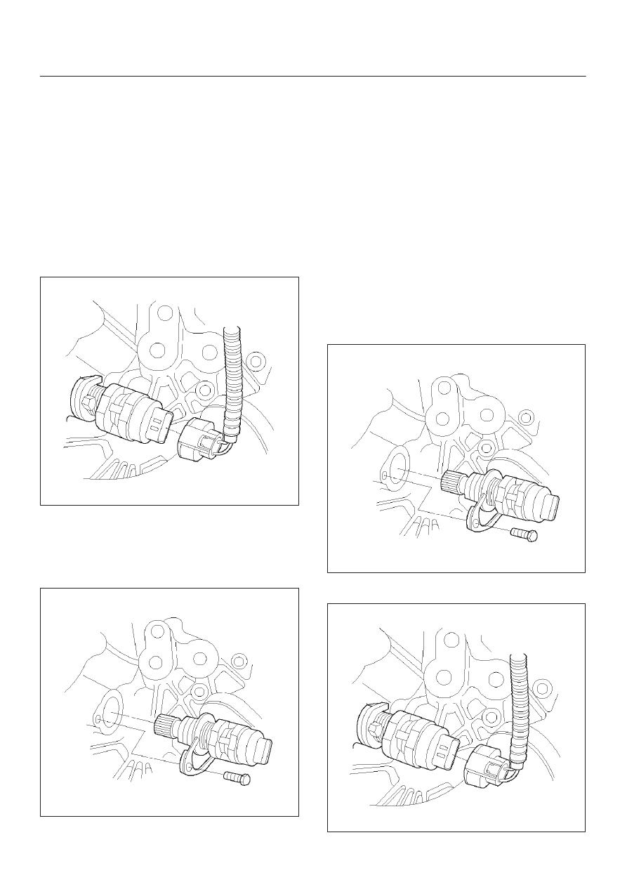
2. Disconnect the VSS electrical connector.

TS23748

3. Remove the bolt and the clamp securing the VSS in

place.

IMPORTANT:

Have a container ready to catch any fluid

that leaks out when the VSS is removed from the transfer
case.

TS23780

4. Remove the VSS from the transfer case by wiggling it

slightly and pulling it straight out.

Inspection Procedure

1. Inspect the electrical connector for signs of corrosion

or warping.  Replace the VSS if the electrical
connector is corroded or warped.

2. Inspect the VSS driven gear for chips, breaks, or worn

condition.  Replace the VSS if the driven gear is
chipped, broken or worn.

3. Inspect the O-ring for wear, nicks, tears, or

looseness.  Replace the O-ring if necessary.

Installation Procedure

1. Install the VSS in the transfer case with the notch for

the connector facing the rear.

2. Secure the VSS in place with the clamp and the bolt.

Tighten

D

Tighten the bolt to 16 N·m (12 lb ft.).

TS23780

3. Connect the VSS electrical connector.

TS23748

6E–303

ENGINE DRIVEABILITY AND EMISSIONS

4. Check the transfer case oil level.  Add fluid if

necessary.

5. Connect the negative battery cable.

Air Cleaner/Air Filter

Removal Procedure

1. Loosen the clamp between the air cleaner lid and the

mass air flow sensor.

2. Release the four latches securing the lid to the air

cleaner housing.

3. Remove the air cleaner lid.

TS23973

4. Remove the air filter element.

TS23794

5. Remove the retaining bolts and the air cleaner

housing from the vehicle.

130RT002

Installation Procedure

1. Install the air cleaner housing in the vehicle with the

retaining bolts.

130RT002

6E–304

ENGINE DRIVEABILITY AND EMISSIONS

2. Install the air filter element in the air cleaner housing.

TS23794

3. Install the air cleaner lid on the MAF sensor and the air

cleaner housing.

TS23973

4. Tighten the clamp and secure the four latches

between the lid and the air cleaner housing.

Idle Air Control (IAC) Valve

Removal Procedure

1. Disconnect the negative battery cable.
2. Disconnect the IAC electrical connector.
3. Remove the bolts and the IAC valve from the throttle

body.

NOTE: Do not clean the IAC valve by soaking it in
solvent.  The valve will be damaged as a result.

TS23745

Cleaning, Inspection, and
Measurement Procedure

D

Clean the IAC valve O-ring sealing surface, pintle
valve seat and air passage.

– Use carburetor cleaner and a parts cleaning brush to

remove carbon deposits.  Do not use a cleaner that
contains methyl ethyl ketone.  This is an extremely
strong solvent and not necessary for this type of
deposit.

– Shiny spots on the pintle are normal and do not

indicate misalignment or a bent pintle shaft.

– If the air passage has heavy deposits, remove the

throttle body for complete cleaning.

TS23746

D

Inspect the IAC valve O-ring for cuts, cracks, or
distortion.  Replace the O-ring if damaged.

6E–305

ENGINE DRIVEABILITY AND EMISSIONS

D

In order to install a new IAC valve, measure the
distance between the tip of the pintle and the
mounting flange.  If that measurement is 28 mm (1.1
in.) or less, the valve needs no adjustment.  If the
measurement is greater than 28 mm (1.1 in.), apply
finger pressure and retract the valve.  The force
required to retract the pintle on a new valve will not
damage the valve, shaft, or pintle.

NOTE: Do not push or pull on the IAC valve pintle on IAC
valves that have been in service.  The force required to
move the pintle may damage it.

IMPORTANT:

Use an identical replacement part in

order to replace a valve.  IAC valve pintle shape and
diameter are designed for the specific application.

TS23746

Installation Procedure

1. Install the IAC valve on the throttle body with the bolts.

Tighten

D

Tighten the bolts to 1 N·m (9 lb in.).

TS23745

2. Connect the IAC valve electrical connector.
3. Install the negative battery cable.

Common Chamber

Removal and Installation Procedure

Refer to Common Chamber in Engine Mechanical.

Accelerator Cable Assembly

Removal Procedure

1. Remove the engine cover.
2. Loosen the adjusting nut on the cable bracket

mounting on the common chamber.

101RW005

3. Remove the accelerator control cable (on the throttle

valve end).

101RW006


Content   ..  1232  1233  1234  1235   ..