Content .. 1207 1208 1209 1210 ..
Opel Frontera UBS. Manual - part 1209
6E–202
ENGINE DRIVEABILITY AND EMISSIONS
Diagnostic Trouble Code (DTC) P0342 CMP Sensor Circuit Low
D06RW032
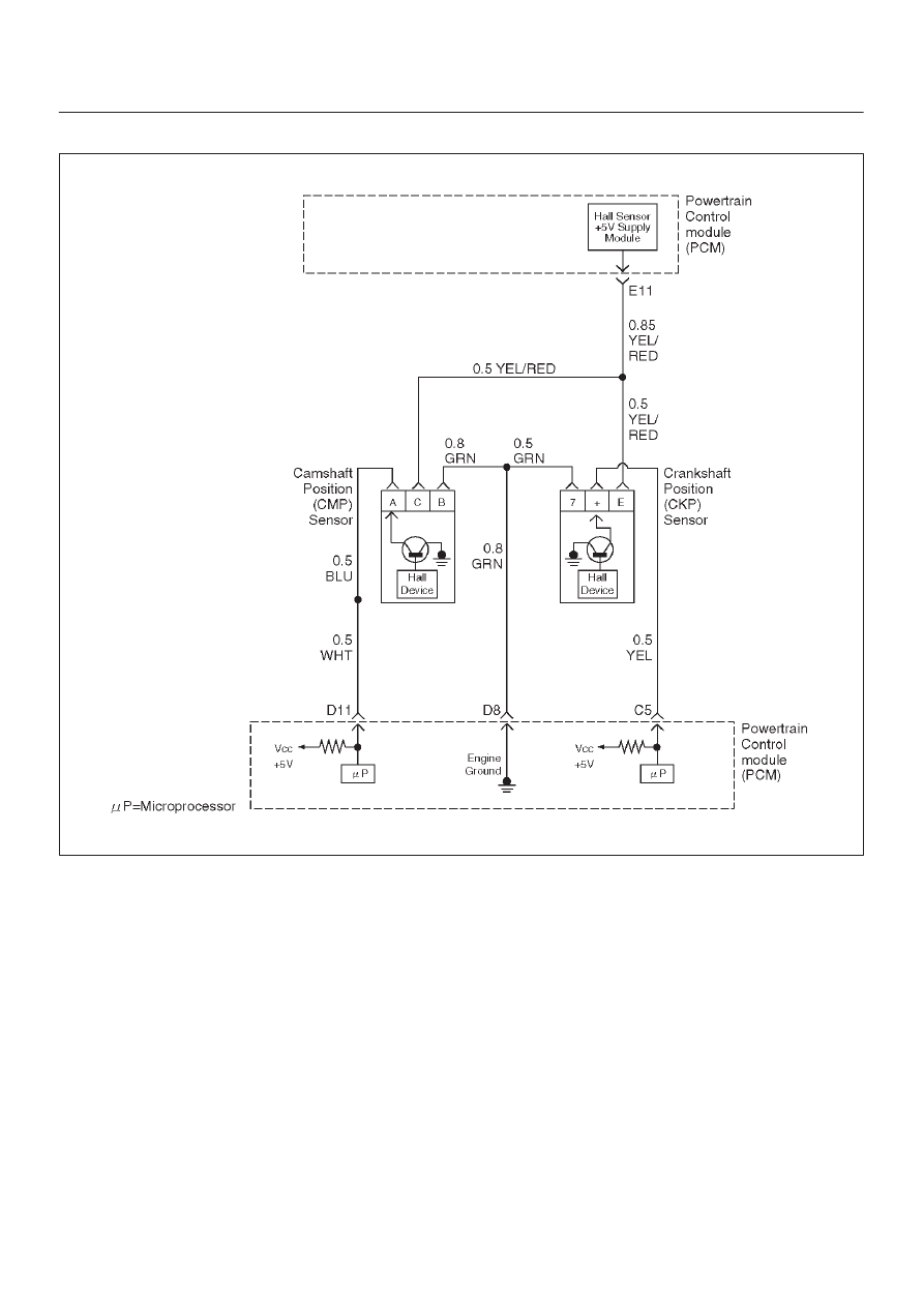
Circuit Description
The CMP signal produced by the camshaft position
(CMP) sensor pulses when the engine is running and
crankshaft position (CKP) sync pulses are also being
received. The hall type CMP sensor and the CKP sensor
share 5 V and ground connections at the powertrain
control module (PCM). The third wire at the sensor is a
signal circuit to the PCM. The PCM uses the CMP signal
pulses to initiate sequential fuel injection. The PCM
constantly monitors the number of pulses on the CMP
signal circuit and compares the number of CMP pulses to
the number of 58X reference pulses received. If the PCM
does not receive pulses on the CMP reference circuit,
DTC P0342 will set and the PCM will initiate injector
sequence without the CMP signal with a one in six chance
that injector sequence is correct. The engine will continue
to start and run normally, although the misfire diagnostic
will be affected if a misfiring condition occurs.
Conditions for Setting the DTC
D
The engine is running.
D
The CMP sensor signal is not received by the PCM
once every 6 cylinders.
D
The above condition occurs for 10 seconds.
Action Taken When the DTC Sets
D
The PCM will illuminate the malfunction indicator lamp
(MIL) after the second consecutive trip in which the
fault is detected.
D
The PCM will initiate injector sequence without the
CMP signal with a one in six chance that the injector
sequence is correct.
D
The PCM will store conditions which were present
when the DTC was set as Freeze Frame and in the
Failure Records data.