Opel Frontera UBS. Manual - part 1206


  Index      Opel     Opel Frontera UBS - service repair manual 1998-2002 year


Search            


Content   ..  1204  1205  1206  1207   ..


Opel Frontera UBS. Manual - part 1206


6E–190

ENGINE DRIVEABILITY AND EMISSIONS

Diagnostic Trouble Code (DTC) P0327 KS Sensor Circuit
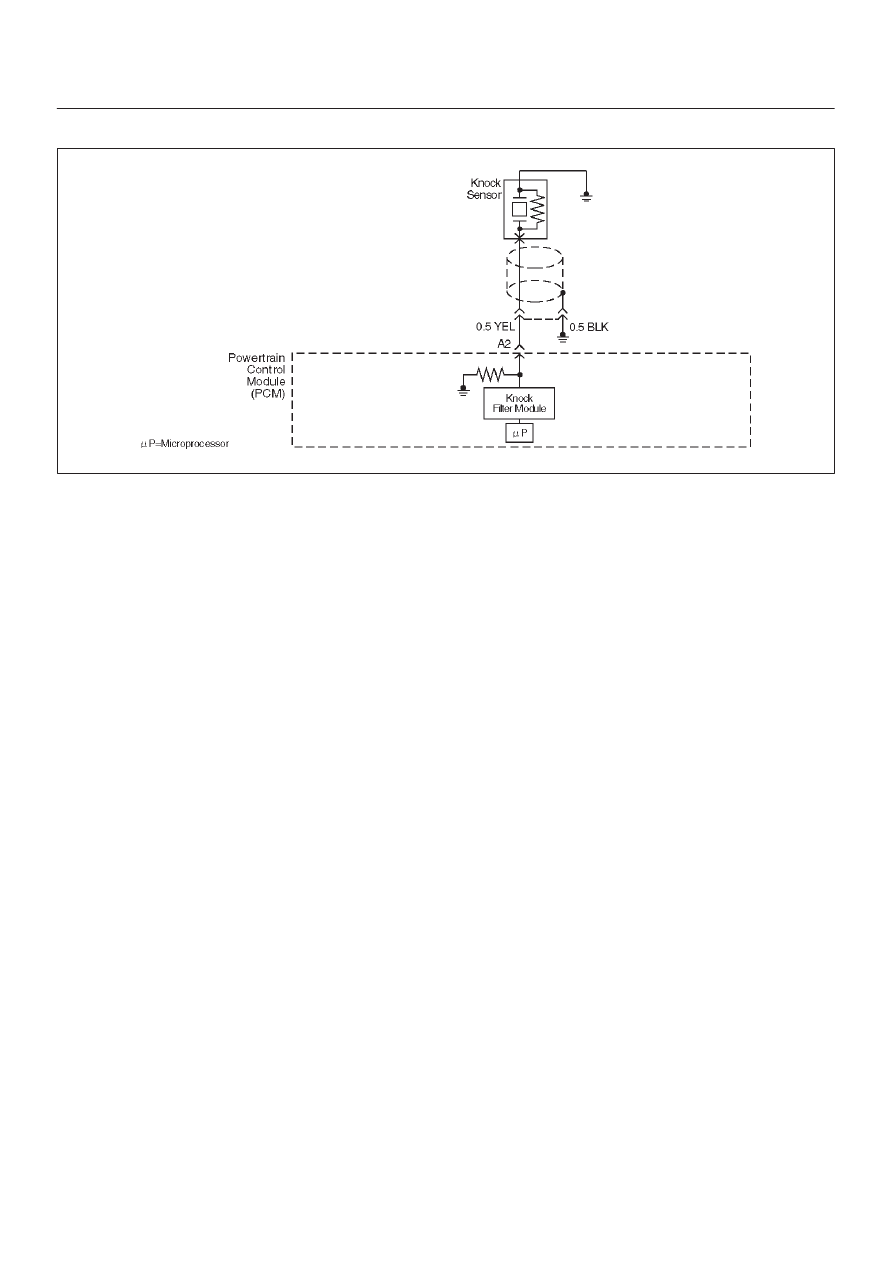
D06RW035

Circuit Description

The powertrain control module (PCM) uses the knock
sensor to detect engine detonation, allowing the PCM to
retard ignition control (IC) spark timing based on the
knock sensor (KS) signal being received.  The knock
sensor produces an AC signal so that under a no knock
condition the signal on the KS circuit measures about
0.007 V AC.  The signal amplitude and frequency are
dependent upon the amount of knock being experienced.
The PCM monitors the KS signal and can diagnose the
KS sensor and circuitry.

Conditions for Setting the DTC

D

Engine running for at least 10 seconds.

D

The TP sensor is greater than 5%.

D

The ECT sensor is greater than 60

°

C (140

°

F).

D

Engine speed is between 2000 and 4000 RPM.

D

The knock sensor signal voltage is less than 0.20 volts,
or greater than 4.8 volts.

D

All conditions are present for more than 15 seconds.

Action Taken When the DTC Sets

D

The PCM will illuminate the malfunction indicator lamp
(MIL) after the second consecutive trip in which the
fault is detected.

D

The PCM will store conditions which were present
when the DTC was set as Freeze Frame and in the
Failure Records data.

D

The PCM will use a calculated spark retard value to
minimize knock during conditions when knock is likely
to occur.  The calculated value will vary based on
engine speed and load.

Conditions for Clearing the MIL/DTC

D

DTC P0327 can be cleared by using Tech 2 “Clear Info”
function or by disconnecting the PCM battery feed.

Diagnostic Aids

Reviewing the Failure Records vehicle mileage since the
diagnostic test last failed may help determine how often
the condition that caused the DTC to be set occurs.  This
may assist in diagnosing the condition.

Test Description

Number(s) below refer to the step number(s) on the
Diagnostic Chart.
2. Ensures that the fault is present.

4. The knock sensor is attached to a short jumper

harness, so it can be tested without removing the
intake manifold.  A 2-wire connector for the knock
sensor is accessible behind the left rear fuel injector.

6E–191

ENGINE DRIVEABILITY AND EMISSIONS

DTC P0327 – KS Sensor Circuit


Step

Action

Value(s)

Yes

No

1

Was the “On-Board Diagnostic (OBD) System Check”
performed?

Go to 

Step 2

Go to 

OBD

System

Check

2

IMPORTANT: If an engine knock can be heard, repair
the engine mechanical problem before proceeding with
this diagnostic.

1. Operate the engine within the conditions specified

in diagnostic support “Conditions for Setting the
DTC.”

2. Using Tech 2, monitor “Specific DTC” info for DTC

P0327 until the DTC P0327 test runs.

3. Note the test result.

Does Tech 2 indicate DTC P0327 failed this ignition?

Go to 

Step 4

Go to 

Step 3

3

1. Ignition “ON,” engine “OFF.”
2. Review and record Tech 2 Failure Records data.
3. Operate the vehicle within Failure Records

conditions.

4. Using Tech 2, monitor “Specific DTC” info for DTC

P0327 until the DTC P0327 test runs.

5. Note the test result.

Does Tech 2 indicate DTC P0327 failed this ignition?

Go to 

Step 4

Refer to

Diagnostic

Aids

4

1. Check for a damaged terminal at the knock sensor

connector.

2. If a problem is found, repair as necessary.

Was a problem found?

Verify repair

Go to 

Step 5

5

Using a test light to battery +, check the black/blue wire
(PCM side) to verify that the shield connection is good.

Did the test light illuminate?

Go to 

Step 7

Go to 

Step 6

6

Repair the open shield ground.

Is the action complete?

Verify repair

7

1. Ignition “OFF,” disconnect the PCM.
2. Check the KS signal circuit for a poor terminal

connection at the PCM.

3. If a problem is found, replace the faulty terminal.

Was a problem found?

Verify repair

Go to 

Step 8

8

1. Ignition “OFF,” PCM disconnected.
2. Check the KS signal circuit between the PCM and

the knock sensor connector for an open, a short to
voltage, or a short to ground.

3. If a problem is found, repair as necessary.

Was a problem found?

Verify repair

Go to 

Step 9

9

1. Ignition “OFF,” PCM disconnected.
2. Knock sensor connected.
3. Measure the resistance of the knock sensor by

connecting the DVM between the PCM connector
and the engine block.

Is the resistance of each knock sensor near the
specified value?

100K ohms

Go to 

Step 10

Go to 

Step 11

6E–192

ENGINE DRIVEABILITY AND EMISSIONS

DTC P0327 – KS Sensor Circuit

  (Cont'd)

Step

No

Yes

Value(s)

Action

10

1. Ignition “OFF,” PCM disconnected.
2. Connect the DVM to monitor AC voltage between

the PCM connector and engine ground.

3. Tap on the engine lift bracket with a socket

extension while observing the signal indicated on
the DVM.

Is any signal indicated on the DVM while tapping on the
engine lift bracket?

Go to 

Step 12

Go to 

Step 11

11

Replace the knock sensor.

Is the action complete?

Verify repair

12

Replace the PCM.

IMPORTANT: The replacement PCM must be
programmed.  Refer to 

UBS 98model year Immobilizer

Workshop Manual.

Is the action complete?

Verify repair

6E–193

ENGINE DRIVEABILITY AND EMISSIONS

Diagnostic Trouble Code (DTC) P0336 58X Reference Signal Circuit

D06RW032

Circuit Description

The 58X reference signal is produced by the crankshaft
position (CKP) sensor.  During one crankshaft revolution,
58 crankshaft pulses will be produced.  The powertrain
control module (PCM) uses the 58X reference signal to
calculate engine RPM and crankshaft position.  The PCM
constantly monitors the number of pulses on the 58X
reference circuit and compares them to the number of
camshaft position (CMP) signal pulses being received.  If
the PCM receives an incorrect number of pulses on the
58X reference circuit, DTC P0336 will set.

Conditions for Setting the DTC

D

Engine is running.

D

Extra or missing pulse is detected between
consecutive 58X reference pulses.

D

Above condition is detected in 10 of 100 crankshaft
rotations.

Action Taken When the DTC Sets

D

The PCM will illuminate the malfunction indicator lamp
(MIL) after the second consecutive trip in which the
fault is detected.

D

The PCM will store conditions which were present
when the DTC was set as Freeze Frame and in the
Failure Records data.

Conditions for Clearing the MIL/DTC

D

DTC P0336 can be cleared by using Tech 2 “Clear Info”
function or by disconnecting the PCM battery feed.

Diagnostic Aids

An intermittent may be caused by a poor connection,
rubbed-through wire insulation or a wire broken inside the
insulation.  Check for:

D

Poor connection - Inspect the PCM harness and
connectors for improper mating, broken locks,
improperly formed or damaged terminals, and poor
terminal-to-wire connection.


Content   ..  1204  1205  1206  1207   ..