Opel Frontera UBS. Manual - part 1194


  Index      Opel     Opel Frontera UBS - service repair manual 1998-2002 year


Search            


Content   ..  1192  1193  1194  1195   ..


Opel Frontera UBS. Manual - part 1194


6E–142

ENGINE DRIVEABILITY AND EMISSIONS

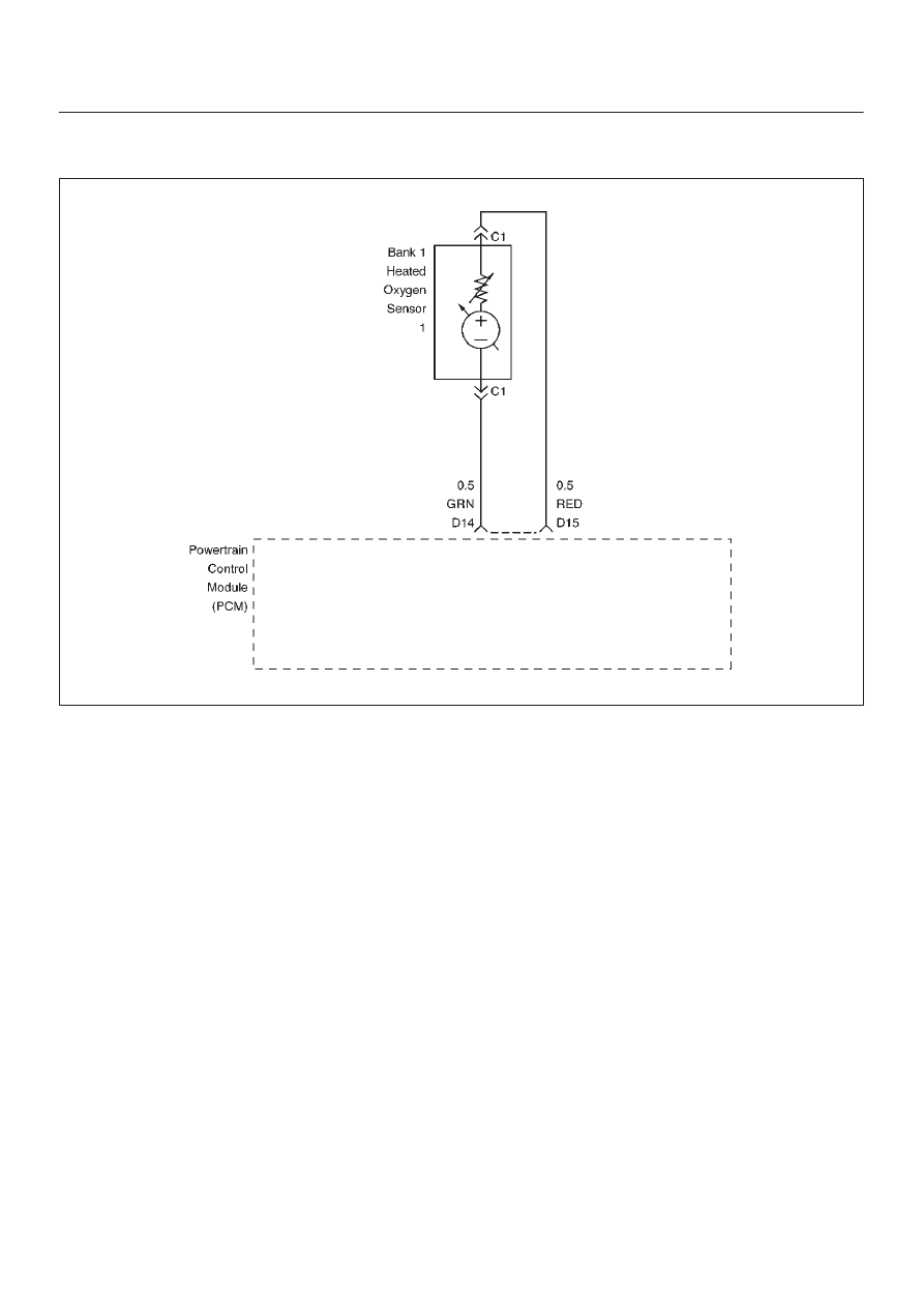
Diagnostic Trouble Code (DTC) P0132 HO2S Circuit High Voltage Bank 1 

Sensor 1

060RW236

Circuit Description

The powertrain control module (PCM) supplies a bias
voltage of about 450 mV between the heated oxygen
sensor (HO2S) signal and low circuits.  When measured
with a 10 megaohm digital voltmeter, this may display as
low as 320 mV.  The oxygen sensor varies the voltage
within a range of about 1000 mV when exhaust is rich,
down through about 10 mV when exhaust is lean.  The
PCM constantly monitors the HO2S signal during “closed
loop” operation and compensates for a rich or lean
condition by decreasing or increasing injector pulse width
as necessary.  If the Bank 1 HO2S 1 voltage remains
excessively high for an extended period of time, DTC
P0132 will be set.

Conditions for Setting the DTC

D

No related DTCs.

D

Engine coolant temperature is above 60

°

C (140

°

F)

D

“Closed loop” commanded air/fuel ratio is between
14.5 and 14.8.

D

Throttle angle is between 3% and 19%.

D

Bank 1 HO2S 1 signal voltage remains above 952 mV
during normal “closed loop” operation for a total of 77
seconds over a 90-second period.

OR

D

Bank 1 HO2S 1 signal voltage remains above 500 mV
during “deceleration fuel cutoff mode” operation for 3
seconds.

Action Taken When the DTC Sets

D

The PCM will illuminate the malfunction indicator lamp
(MIL) the first time the fault is detected.

D

The PCM will store conditions which were present
when the DTC was set as Freeze Frame and in the
Failure Records data.

D

“Open loop” fuel control will be in effect.

Conditions for Clearing the MIL/DTC

D

DTC P0132 can be cleared by using the Tech 2 “Clear
Info” function or by disconnecting the PCM battery
feed.

Diagnostic Aids

Check the following items:

D

Fuel pressure – The system will go rich if pressure is
too high.  The PCM can compensate for some
increase.  However, if fuel pressure is too high, a DTC
P0132 may be set.  Refer to 

Fuel System Diagnosis.

D

Perform “Injector Balance Test” – Refer to 

Fuel System

Diagnosis.

D

MAF sensor –The system can go rich if MAF sensor
signal indicates an engine airflow measurement that is
not correct.  Disconnect the MAF sensor to see it the
rich condition is corrected.  If so, replace the MAF
sensor.

D

Check for a leak in the fuel pressure regulator
diaphragm by checking the vacuum line to the
regulator for the presence of fuel.  There  should be no
fuel in the vacuum line.

6E–143

ENGINE DRIVEABILITY AND EMISSIONS

D

An intermittent TP sensor output will cause the system
to go rich due to a false indication of the engine
accelerating.

D

Shorted Heated Oxygen Sensor (HO2S) –If the HO2S
is internally shorted, the HO2S voltage displayed on
the Tech 2 will be over 1 volt.  Try disconnecting the
affected HO2S with the key “ON,” engine “OFF.”  If the
displayed HO2S voltage changes from over 1000 mV
to around 450 mV, replace the HO2S.  Silicon
contamination of the HO2S can also cause a high
HO2S voltage to be indicated.  This condition is
indicated by a powdery white deposit on the portion of
the HO2S exposed to the exhaust stream.  If
contamination is noticed, replace the affected HO2S.

D

Open HO2S Signal Circuit or Faulty HO2S–A poor
connection or open in the HO2S signal circuit can
cause the DTC to set during deceleration fuel mode.
An HO2S which is faulty and not allowing a full voltage
swing between the rich and lean thresholds can also
cause this condition.  Operate the vehicle by
monitoring the HO2S voltage with a Tech 2.  If the

HO2S voltage is limited within a range between 300
mV to 600 mV, check the HO2S signal circuit wiring
and associated terminal conditions.

D

If none of the above conditions are present, replace the
affected HO2S.

Test Description

Number(s) below refer to the step number(s) on the
Diagnostic Chart.
3. DTC P0132 failing during “deceleration fuel cutoff

mode” operation may indicate a condition described
in the “Diagnostic Aids” above.  If the DTC P0132
test passes while the Failure Records conditions are
being duplicated, an intermittent condition is
indicated.  

Reviewing the  Failure Records vehicle mileage since the
diagnostic test last failed may help determine how often
the condition that caused the DTC to be set occurs.  This
may assist in diagnosing the condition.

DTC P0132 – HO2S Circuit  High Voltage Bank 1 Sensor 1


Step

Action

Value(s)

Yes

No

1

Was the “On-Board Diagnostic (OBD) System Check”
performed?

Go to 

Step 2

Go to 

OBD

System

Check

2

1. Install the Tech 2.
2. Run the engine at operating temperature.
3. Operate the vehicle within parameters specified

under “Conditions for Setting the DTC” included in
Diagnostic Support.

4. Using a Tech 2, monitor Bank 1 HO2S 1 voltage.

Does the Bank 1 HO2S 1 voltage remain above the
specified value?

952 mV (500

mV in

deceleration

fuel cutoff

mode)

Go to 

Step 4

Go to 

Step 3

3

1. Ignition “ON,” review and record Tech 2 Failure

Records data.

2. Operate the vehicle within Failure Records

conditions as noted.

3. Using a Tech 2, monitor “Specific DTC” info for DTC

P0132 until the DTC P0132 test runs.

4. Note the test result.

Does the Tech 2 indicate DTC P0132 failed this
ignition?

Go to 

Step 4

Refer to

Diagnostic

Aids

4

1. Ignition “OFF.”
2. Disconnect Bank 1 HO2S 1.
3. Ignition “ON.”
4. At HO2S Bank 1 Sensor 1 connector (PCM side)

use a DVM to measure voltages at the high and low
signal terminals.

Are the voltages in the specified range?

3-4 V

Go to 

Step 5

Go to 

Step 6

5

Repair short to voltage in signal circuit.

Is the action complete?

Verify repair

6E–144

ENGINE DRIVEABILITY AND EMISSIONS

DTC P0132 – HO2S Circuit  High Voltage Bank 1 Sensor 1

  (Cont'd)

Step

No

Yes

Value(s)

Action

6

1. Ignition “ON,” engine“OFF.”
2. At Bank 1 HO2S 1 connector (PCM side) jumper

both the HO2S high and low signal circuits (PCM
side) to ground.

3. Using a Tech 2, monitor Bank 1 HO2S 1 voltage.

Is Bank 1 HO2S 1 voltage below the specified value?

10 mV

Go to 

Step 7

Go to 

Step 8

7

1. Disconnect the jumpers to ground from Bank 1

HO2S 1 PCM-side connector.

2. With the HO2S 1 connector disconnected, monitor

Bank 1 HO2S 1 voltage.

Is Bank 1 HO2S 1 voltage between the specified
values?

425-475 mV

Refer to

Diagnostic

Aids

Go to 

Step 8

8

Replace the PCM.

IMPORTANT: The replacement PCM must be
programmed.  Refer to 

UBS 98model year Immobilizer

Workshop Manual.

Is the action complete?

Verify repair

6E–145

ENGINE DRIVEABILITY AND EMISSIONS

Diagnostic Trouble Code (DTC) P0134 HO2S Circuit Insufficient Activity Bank 1

Sensor 1

060RW237

Circuit Description

D

The powertrain control module (PCM) supplies a bias
voltage of about 450 mV between the heated oxygen
sensor (HO2S) high and low circuits.  When measured
with a 10 megaohm digital voltmeter, this may display
as low as 320 mV.  The oxygen sensor varies the
voltage within a range of about 1000 mV when the
exhaust is rich, down through about 10 mV when
exhaust is lean.  The PCM constantly monitors the
HO2S signal during “closed loop” operation and
compensates for a rich or lean condition by decreasing
or increasing injector pulse width as necessary.  If the
Bank 1 HO2S 1 voltage remains at or near the 450 mV
bias for an extended period of time, DTC P0134 will be
set, indicating an open sensor signal or sensor low
circuit.

D

Heated oxygen sensors are used to minimize the
amount of time required for “closed loop” fuel control
operation and to allow accurate catalyst monitoring.
The oxygen sensor heater greatly decreases the
amount of time required for fuel control sensors Bank
1 HO2S 1 and Bank 2 HO2S 1 to become active.

D

Oxygen sensor heaters are required by post-catalyst
monitor sensors to maintain a sufficiently high
temperature for accurate exhaust oxygen content
readings further from the engine.

Conditions for Setting the DTC

D

No related DTCs.

D

Battery voltage is above 10 volts.

D

Engine run time is longer than 40 seconds.

D

Oxygen sensor heater has been determined to be
functioning properly.

D

Bank 1 HO2S 1 signal voltage remains between
400 mV and 500 mV for a total of 77 seconds over a
90-second period of time.

Action Take When the DTC Sets

D

The PCM will illuminate the malfunction indicator lamp
(MIL) the first time the fault is detected.

D

The PCM will store conditions which were present
when the DTC was set as Freeze Frame and in the
Failure Records data.

D

“Open loop” fuel control will be in effect.

Conditions for Clearing the MIL/DTC

D

DTC P0134 can be cleared by using Tech 2 “Clear Info”
function or by disconnecting the PCM battery feed.

Diagnostic Aids

Check for the following conditions:

D

Poor connection or damaged harness – Inspect the
harness connectors for backed-out terminals,
improper mating, broken locks, improperly formed or
damaged terminals, poor terminal-to-wire connection,
and damaged harness.

D

Faulty HO2S heater or heater circuit – With the ignition
“ON,” engine “OFF,” after a cool down period, the
HO2S 1 voltage displayed on Tech 2 is normally
455-460 mV.  A reading over 1000 mV indicates a
signal line shorted to voltage.  A reading under 5 mV


Content   ..  1192  1193  1194  1195   ..