Content .. 1125 1126 1127 1128 ..
Opel Frontera UBS. Manual - part 1127
6A–35
ENGINE MECHANICAL
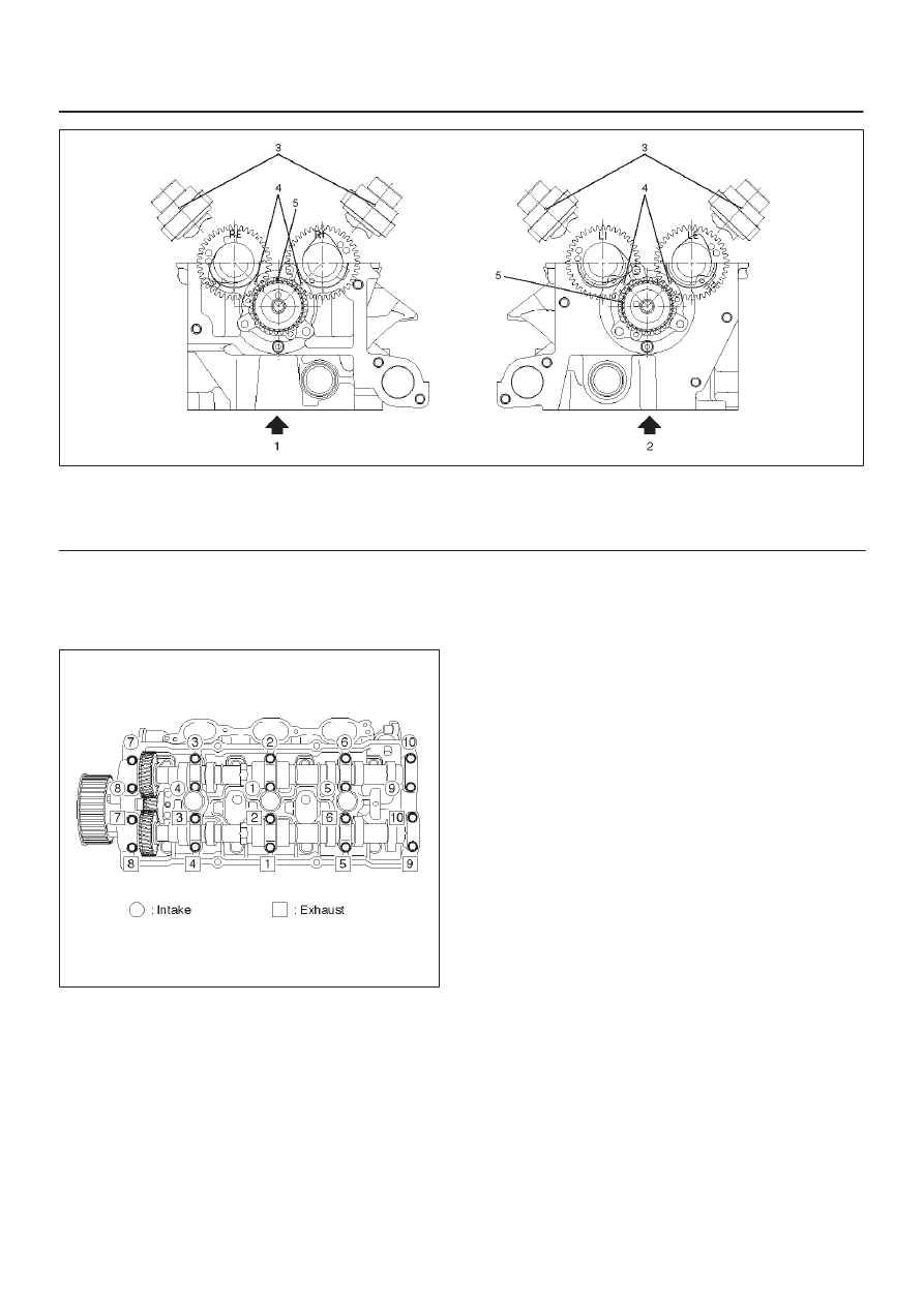
014RW024
Legend
(1) Right Bank
(2) Left Bank
(3) Alignment Mark on Camshaft Drive Gear
(4) Alignment Mark on Camshaft
(5) Alignment Mark on Retainer
3. Tighten twenty bolts on numerical order an one
side bank as shown in the illustration.
Torque : 10 N·m (1.0 Kg·m/89 lb in)
014RW031
5. Install cylinder head cover RH.
D
Refer to installation procedure for CYLINDER
HEAD COVER RH in this manual.
6. Install cylinder head cover LH.
D
Refer to installation procedure for CYLINDER
HEAD COVER LH in this manual.
7. Install timing belt.
D
Refer to installation procedure for TIMING BELT in
this manual.
8. Install crankshaft pulley.
D
Refer to installation procedure for CRANKSHAFT
PULLEY in this manual.
Accelerator pedal cable adjustment
1. Loosen adjusting nut and lock nut.
2. Pull outer cable while closing fully the throttle
valve.
3. Tighten adjusting nut and lock nut temporarily.