Index Opel Opel Frontera UBS - service repair manual 1998-2002 year
Search
Content .. 1035 1036 1037 1038 ..
Opel Frontera UBS. Manual - part 1037
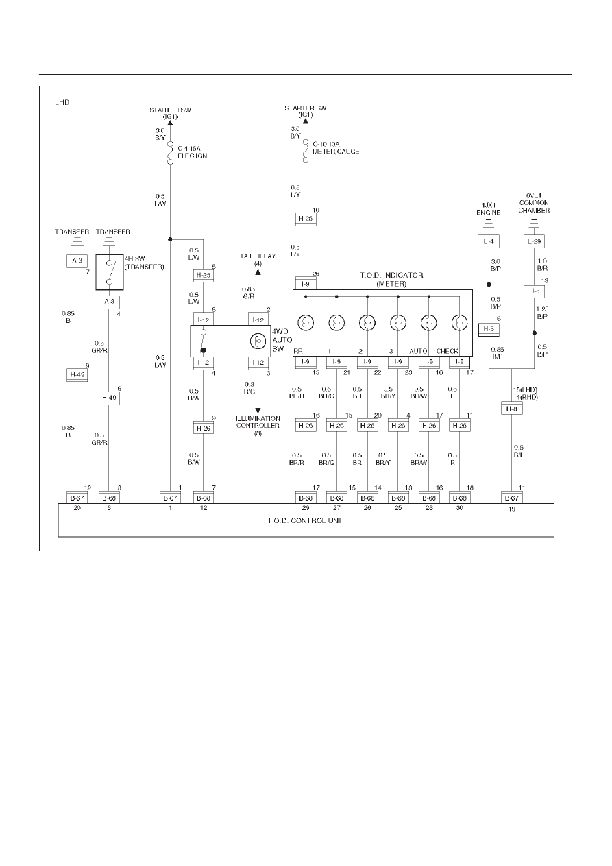
DRIVE LINE CONTROL SYSTEM (TOD)
4B2–88
D04RY00115