Opel Frontera UBS. Manual - part 1024


  Index      Opel     Opel Frontera UBS - service repair manual 1998-2002 year


Search            


Content   ..  1022  1023  1024  1025   ..


Opel Frontera UBS. Manual - part 1024


DRIVE LINE CONTROL SYSTEM (TOD)

4B2–36

Checking Failed Pin

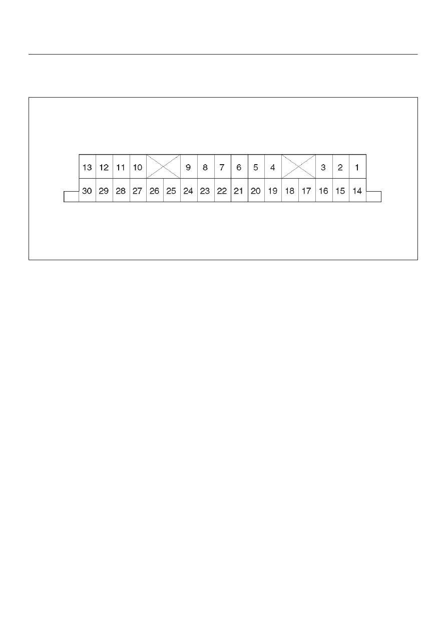
Connector Pin Assignment

D

ECU pin assignment

D04RW032

4B2–37

DRIVE LINE CONTROL SYSTEM (TOD)

No.

NAME

CONTENTS

1

VIG

Power supply (IG)

2

N.C

Not used

3

4WD OUT

4WD signal output

4

SOL (+)

Electromagnetic solenoid

5

ADC (+)

Axle disconnect output

6

LIGHTING SW

Lighting SW input

7

BRAKE

Brake SW input

8

4H SW

4H SW input

9

4L SW

4L SW input

10

AXEL SW

AXEL SW input

11

ABS IN

Operation signal input

12

TOD SW

TOD SW input

13

DIAG

Self-diagnosis input

14

D-G MAP

D-G MAP recognition input (Only V6 engine)

15

Ref.

Vehicle speed sensor supply

16

N.C

Not used

17

N.C

Not used

18

COM (–)

Vehicle speed sensor GND

19

S-GND

Sensor GND

20

P-GND

Power GND

21

TPS

Throttle position sensor

22

TECH 2

TECH 2 output

23

Rer. Sig

Rear vehicle speed sensor input

24

Frt. Sig

Front vehicle speed sensor input

25

IND.a

4WD display signal a

26

IND.b

4WD display signal b

27

IND.c

4WD display signal c

28

IND.AUTO

AUTO display output

29

IND Rr

Rear display output

30

CHECK

TOD warning lamp

DRIVE LINE CONTROL SYSTEM (TOD)

4B2–38

Reference

D

Transfer connector pin assignment (connector on the
transfer case)
for inspection of transfer pins.

810RW310

No.

NAME

CONTENTS

1

Ref. (Rer. )

Rear speed sensor reference output

2

Ref. (Frt. )

Front speed sensor reference output

3

SW GND

SW GND

4

4H SW (+)

4H SW plus terminal

5

Rer. (+)

Rear speed sensor plus

6

Frt. (+)

Front speed sensor plus

7

POWER GND

Power GND

8

SOL (+)

Electromagnetic solenoid

9

COM (–) (Rer. )

Rear speed sensor GND

10

COM (–) (Frt. )

Front speed sensor GND

11

NC

Not used

12

4L SW (+)

4L SW plus terminal

4B2–39

DRIVE LINE CONTROL SYSTEM (TOD)

Checking Failed TOD Control Unit Pin

NOTE:

1. Unplug the ECU connector and the pins, unless

otherwise specified.

2. Before removing the ECU, turn off the ignition switch.
3. If the standard values are not observed, check the

pins with other testers.

Check

Pin

No.

Circuit to be

tested

Ignition

Switch

Position

Engine

State

Multimeter

Scale/

Range

Measure 

between Pin

Number

Standard Valve

Note

14

D-G MAP

OFF

STOP

W

14, 19

Continuity : OK
(Gasoline)
No continuity : OK
(Diesel)

20

P-GND

OFF

STOP

W

20, 19

Continuity : OK

19

GND

OFF

STOP

W

19, GND

Continuity : OK

8

4H SW

OFF

STOP

W

8, 19

No continuity (high,
4L) and continuity
(N) : OK

9

4L SW

OFF

STOP

W

9, 19

No continuity (high)
and continuity (4L,
N) : OK

10

AXLE SW

ON

RUN

W

10, 19

Continuity : OK

Remove ECU and start the engine.  Move
the vehicle forth and back to connect axle
surely.

13

DIAG

OFF

STOP

W

13 (TOD), 8

(DLC 

Connector)

Continuity : OK

DLC connector terminal 8

25

IND.a

ON

STOP

DCV

25 (+), 19 (–)

8.0 

14.5 V

When the indicator lamp is turned off.

26

IND.b

ON

STOP

DCV

26 (+), 19 (–)

8.0 

14.5 V

When the indicator lamp is turned off.

27

IND.c

ON

STOP

DCV

27 (+), 19 (–)

8.0 

14.5 V

When the indicator lamp is turned off.

30

CHECK

LAMP

ON

STOP

DCV

30 (+), 19 (–)

8.0 

14.5 V

When the indicator lamp is turned off.

11

ABS IN

ON

STOP

DCV

11 (+), 19 (–)

11.5 

14.5 V

15

Ref.

ON

STOP

DCV

15 (+), 19 (–)

9 V

Connect ECU

24

Ft.(+)

ON

STOP

DCV

24 (+), 19 (–)

0.7 

6 V

Connect ECU (off one tooth of speed 
sensor ring) and move the vehicle making
sure of voltage change.

23

Rr.(+)

ON

STOP

DCV

23 (+), 19 (–)

0.7 

6 V

Connect ECU (off one tooth of speed 
sensor ring) and move the vehicle making
sure of voltage change.

18

COM(-)

ON

STOP

DCV

18 (+), 19 (–)

0V

Connect ECU

1

Vig

ON

STOP

DCV

1 (+), 19 (–)

14.5 V

7

BRAKE

OFF

STOP

DCV

7 (+), 19 (–)

14.5 V

Press brake pedal

21

TPS

ON

STOP

DCV

21 (+), 19 (–)

0.2 

4.6 V

Step on the accelerator pedal and make
sure that voltage changes.

3

4WD OUT

OFF

STOP

W

3, 19

12 k

W

Disconnect battery GND terminal

5

ADC(+)

OFF

STOP

W

5, 19

10 

30 

W

Disconnect battery GND terminal

4

SOL(+)

OFF

STOP

W

4, 19

1.0 

5.0 

W

Disconnect battery GND terminal

12

4WD SW

ON

STOP

DCV

12 (+), 19 (–)

SW OFF : 0 V
SW ON : 8.0 

14.5 V

SW OFF : Contact point open
SW ON : Contact point close

6

LIGHTING

ON

STOP

DCV

6 (+), 19 (–)

SW OFF : 8.0 

14.5

V
SW ON : 0 V

28

AUTO INDI

ON

STOP

DCV

28 (+), 19 (–)

TOD : 0 V
2H & 4L : 8.0 

14.5

V

Connect ECU

29

RR INDI

ON

STOP

DCV

29 (+), 19 (–)

0 V

Connect ECU. When the indicator lamp is
turned on.


Content   ..  1022  1023  1024  1025   ..