Opel Frontera UBS. Manual - part 1013


  Index      Opel     Opel Frontera UBS - service repair manual 1998-2002 year


Search            


Content   ..  1011  1012  1013  1014   ..


Opel Frontera UBS. Manual - part 1013


4B1–30DRIVE LINE CONTROL SYSTEM (SHIFT ON THE FLY)

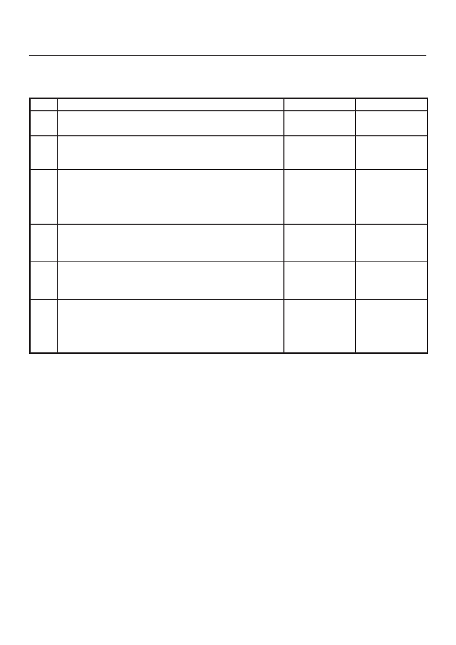
Front Axle Diagnosis

D

When the 4WD switch is operated from 4H to 2H,
indicator light does not go out.

Step

Action

Yes

No

1

Drive slow 100 — 200m after a few minutes” idling.

Has indicator light gone out?

All right.

Go to Step 2

2

Jack up front tires.

Does the right side of front wheel rotate when the left side of front
wheel is rotated?

Go to Step 4

Go to Step 3

3

1. Check the actuator switch.
2. Check the circuit to indicator.

Was a problem found?

Trace this chart

from the start

after repair or

replace.

Disassemble axle

ASM for check.

Trace this chart

from the start

after repair or

replace.

4

1. Check the VSV valve.
2. Check the circuit to VSV valve.

Was a problem found?

Trace this chart

from the start

after repair or

replace.

Go to Step 5

5

Is vacuum piping all right? (tank, hose, & pipe damage or trouble)

Go to Step 6

Trace this chart

from the start

after repair or

replace.

6

Does actuator work all right?

Trace this chart

from the start.

Disassemble axle

ASM for check.

Trace this chart

from the start

after repair or

replace.

4B1–31

DRIVE LINE CONTROL SYSTEM (SHIFT ON THE FLY)

D

When the 4WD switch is operated from 2H to 4H,
indicator light is not actuated.

Step

Action

Yes

No

1

Drive slow 100 — 200m after a few minutes” idling.

Has indicator light actuated?

All right.

Go to Step 2

2

Jack up front tires.

Does not the right side of front wheel rotate when the left side of
front wheel is rotated?

Go to Step 4

Go to Step 3

3

1. Check the actuator switch.
2. Check the circuit to indicator.

Was a problem found?

Trace this chart

from the start

after repair or

replace.

Disassemble axle

ASM for check.

Trace this chart

from the start

after repair or

replace.

4

1. Check the VSV valve.
2. Check the circuit to VSV valve.

Was a problem found?

Trace this chart

from the start

after repair or

replace.

Go to Step 5

5

Is vacuum piping all right? (tank, hose, & pipe damage or trouble)

Go to Step 6

Trace this chart

from the start

after repair or

replace.

6

Does actuator work all right?

Trace this chart

from the start.

Disassemble axle

ASM for check.

Trace this chart

from the start

after repair or

replace.

4B1–32DRIVE LINE CONTROL SYSTEM (SHIFT ON THE FLY)

Shift on the Fly Vacuum Piping and Electric Equipment 

(For Push Button Type)

Vacuum Piping Diagram

C04RW013

VSV Assembly, Actuator Assembly

412RS032

Vacuum Tank

412RS033

4B1–33

DRIVE LINE CONTROL SYSTEM (SHIFT ON THE FLY)

Inspection and Repair

Vacuum Piping

C04RW014

1. Pull out the Hose A in figure and install a vacuum

gauge.

2. Plug up Hose B in figure to prevent the leak of

vacuum.

3. Start the engine and measure vacuum 2 or 3 minutes

afterward.

4. Repeat 1) and 2) but with Hose A plugged and Hose B

pulled out.

5. If vacuum measures –400mmHg, or if it shows a

sudden drop immediately after engine stop, inspect
the hose, tank, and pipe for damage.

NOTE: Be careful not to permit the entry of dust and
water during inspection.

6. Pull out Hose D in above illustration.
7. Plug Hose E in above illustration.
8. Make sure that Hose D in above illustration is under

atmospheric pressure.

9. Pull out Hose E and plug Hose D, and make sure that

Hose E is under atmospheric pressure.

10. If Check 8) or 9) has revealed stoppage, check and

see that there is no bend, foreign matter in the hose or
in the filter. If there is trouble, repair or replace.

Check Valve

C04RS004

1. Apply vacuum from the orange colored side(1).

Vacuum:–400mmHg

2. Check leakage of vacuum.
3. Make sure that vacuum cannot be applied from the

black colored side(2).


Content   ..  1011  1012  1013  1014   ..