Opel Frontera UBS. Manual - part 88


  Index      Opel     Opel Frontera UBS - service repair manual 1998-2002 year


Search            


Content   ..  86  87  88  89   ..


Opel Frontera UBS. Manual - part 88


SUPPLEMENTAL RESTRAINT SYSTEM STEERING WHEEL & COLUMN  2A – 73
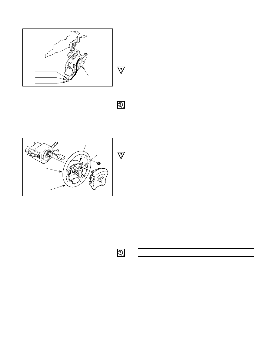
Starter switch 
harness
Combination
switch harness
Inflator module
 harness

Setting cowl
(Lower)

7. Steering Column Cover

When installing the steering column cover, be sure to
route each wire harness as illustrated so that the
harnesses do not catch on any moving parts.

6. Steering Wheel

Align the setting marks made when removing.

CAUTION:
Never apply force to the steering wheel in direction of the
shaft by using a hammer or other impact tools in an
attempt to remove the steering wheel.  The steering shaft
if designed as an energy absorbing unit.

Tighten the steering wheel fixing nut to the specified
torque.

Steering Wheel Nut Torque

N·m (kg·m/lb·ft)

34 (3.5 / 25)

5. Inflator Module

1) Support the module and carefully connect the

module connector.

CAUTION:

Never use the air bag assembly from another vehicle.
Use only the air bag assembly for "UBS".

When replace the inflator module, use only same parts
number assembly. If different parts number assembly is
installed, the air bag system can not function correctly
because it has different characteristic.

NOTE:
Pass the lead wire through the tabs on the plastic
cover (wire protector) of inflator to prevent lead wire
from being pinched.

2) Secure the module with one bolt to relieve

weight on the connector wire.

3) Tighten bolts to specified sequence as figure.

Inflator Module Bolt Torque

N·m (kg·m/lb·in)

8 (0.8 / 69)

4

Driver Knee Bolster (Reinforcement)

3. Steering Lower Cover

Install the engine hood opening lever.

2. Lower Cluster Assembly

1. Front Console Assembly

Connect the wiring harness connectors.
Install the transmission (for M/T) and transfer control
lever knob.

Connect the yellow 2way SRS connector located
under the steering column.

Connect the battery ground cable.

825RS048

3

4

1

2

827RS017

2A – 74 SUPPLEMENTAL RESTRAINT SYSTEM STEERING WHEEL & COLUMN

SYSTEM INSPECTION

Turn the ignition to "ON" while watching warning
light.

Light should flash 7 times and then go off.  If lamp
does not operate correctly, refer to Section 9J.

SUPPLEMENTAL RESTRAINT SYSTEM STEERING WHEEL & COLUMN  2A – 75

SECTION 2A

STEERING COLUMN

CONTENTS

PAGE

General Description ......................................................................................................... 2A – 76

On-Vehicle Service........................................................................................................... 2A – 77

Steering Wheel Replacement ..................................................................................... 2A – 77

Combination Switch Replacement ............................................................................ 2A – 79

Lock Cylinder Replacement ........................................................................................ 2A – 81

Steering Column Replacement .................................................................................. 2A – 84

2A – 76 SUPPLEMENTAL RESTRAINT SYSTEM STEERING WHEEL & COLUMN

GENERAL DESCRIPTION

The steering column has three important features in
addition to the steering function:

1.

The column is energy absorbing, designed to
compress in a front-end collision to minimize
the possibility of injury to the driver of the
vehicle.

2.

The ignition switch and lock are mounted
conveniently on the column.

3.

With the column mounted lock, the ignition
and steering operation can be locked to
prevent theft of the vehicle.

The column may be disassembled and
reassembled.  To insure the energy absorbing
action, it is important that the specified screws,
bolts and nuts be used only as designated and that
they are tightened to the specified torque.

When the column is removed from the vehicle, a
sharp blow on the end of steering shaft leaning on
the column assembly, or dropping the assembly
could shear or loosen the fasteners that maintain
column rigidity.


Content   ..  86  87  88  89   ..