Opel Frontera UBS. Manual - part 64


  Index      Opel     Opel Frontera UBS - service repair manual 1998-2002 year


Search            


Content   ..  62  63  64  65   ..


Opel Frontera UBS. Manual - part 64


COMPRESSOR OVERHAUL  1D – 23

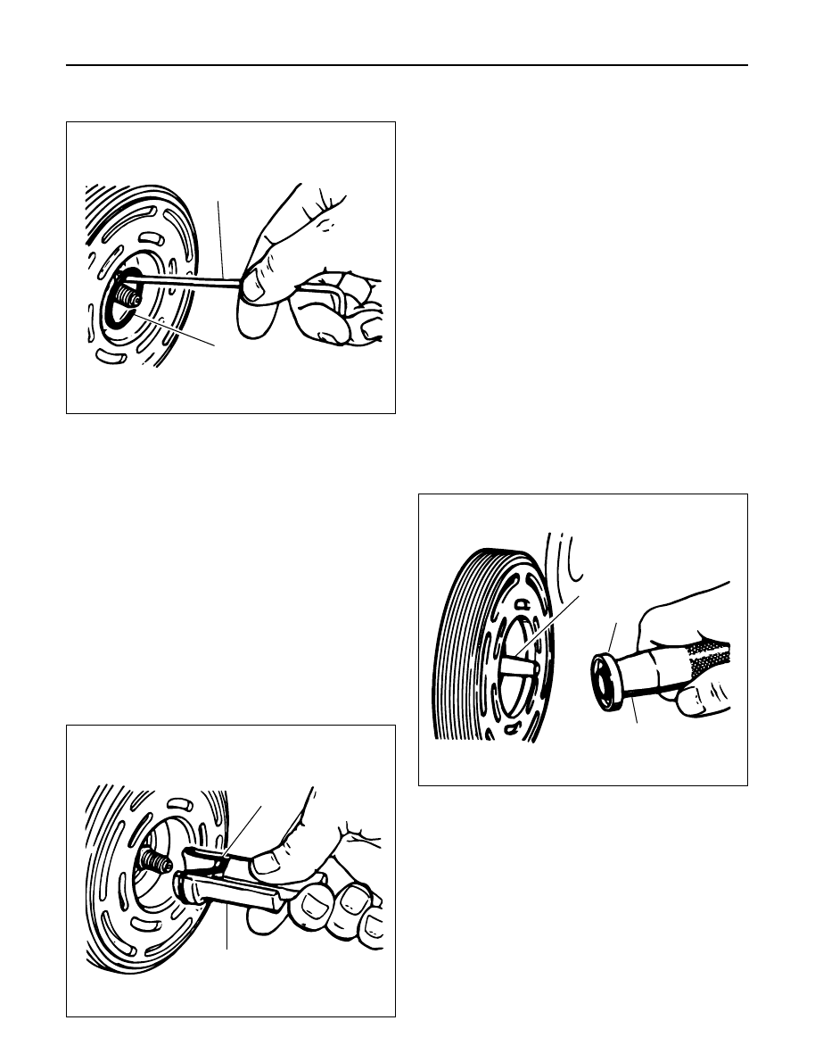
7. Remove and discard the seal seat O-ring (2) from the

compressor neck using O-ring remover J-9553-01.

8. Recheck the shaft and inside of the compressor

neck for dirt or foreign material and be sure these
areas are perfectly clean before installing new parts. 

Cleaning

Thoroughly clean O-ring seal groove in front head.

CAUTION: Seals should not be re-used. Always use
a new specification service seal on rebuild. Be sure
that the seal to be installed is not scratched or
damaged in anyway. Make sure that the seal seat
and seal are free of lint and dirt that could damage
the seal surface or prevent sealing.

Installation

1. Dip the new seal seat O-ring (1) in clean 525

viscosity refrigerant oil and assemble onto O-ring
installer J-33011.

2. Insert the O-ring installer J-33011 into the

compressor neck until the installer "bottoms". Lower
the moveable slide of the O-ring installer to release
the O-ring into the seal O-ring lower groove (The
compressor neck top groove is for the shaft seal
retainer ring.) Rotate the installer to seat the O-ring
and remove the installer.

3. Dip the new seal in clean 525 viscosity refrigerant oil

and assemble seal to Seal Installer J-23128-A, by
turning handle clockwise. The stamped steel case
side of the lip seal must be engaged with knurled
tangs of installer so that flared-out side of lip seal is
facing and installed towards the compressor. Install
seal protector J-34614, in the seal lip and place over
the compressor shaft, and push the seal in place with
a rotary motion or place the seal protector J-34614
over end of compressor shaft, and slide the new seal
onto the shaft with a rotary motion until it stops. Take
care not to dislodge the O-ring. Be sure the seal (2)
makes good contact with the O-ring. Disengage the
installer from the seal and remove the installer 
J-23128-A and the seal protector J-34614.

CAUTION: Handling and care of seal protector is
important. If seal protector is nicked or the bottom
flared, the new seal may be damaged during
installation.

4. Install the new seal retainer ring with its flat side

against the Seal, using Snap-Ring Pliers. Use the
sleeve from O-ring installer J-33011 to press in on
the seal retainer ring so that it snaps into its groove.

5. To leak test, install compressor leak test fixture 

J-39893 on rear head of compressor and connect
gage charging lines and Refrigerant Recovery
System. Pressurize suction and high-side of
compressor with R-134a Refrigerant. Temporarily
install (M9 

×

1.25 thread on shaft) nut and, with the

compressor in horizontal position, rotate the
compressor shaft in normal direction of rotation
several times by hand. Leak test the seal area and
correct and leak found. Recover the refrigerant.
Remove shaft nut.

2

J-9553-01

901RW009

1

J-33011

901RW010

J-34614

2

J-23128-A

901RW011

1D – 24 COMPRESSOR OVERHAUL

6. Remove any excess oil resulting from installing the

new seal parts from the shaft and inside the
compressor neck.

7. Install the clutch plate and hub assembly as

described previously.

8. Reinstall compressor belt and tighten bracket.

9. Evacuate and charge the refrigerant system.

COMPRESSOR PRESSURE RELIEF VALVE

Removal

1. Recover the refrigerant using Refrigerant Recovery

System.

2. Remove old pressure relief valve.

Installation

1. Clean valve seat area on rear head.

2. Lubricate O-ring of new pressure relief valve and

O-ring assembly with new 525 viscosity refrigerant
oil. Install new valve and torque in place, 9.0 N·m
(6.1 ft lbs)

3. Evacuate and recharge the system.

4. Leak test system.

COMPRESSOR OIL

Compressor Oil Check

The oil used to lubricate the compressor is circulating
with the refrigerant.
Whenever replacing any component of the system or a
large amount of gas leakage occurs, add oil to maintain
the original amount of oil.

Checking and Adjusting Oil Quantity for
Used Compressor

1. Perform oil return operation. Refer to Oil Return

Operation in this section.

2. Discharge and recover refrigerant and remove the

compressor.

3. Drain the compressor oil and measure the extracted

oil with a measuring cylinder.

4. If the amount of oil drained is much less than 90 cc

(3.0 fl. oz.), some refrigerant may have leaked out.
Conduct a leak tests on the connections of each
system, and if necessary, repair or replace faulty
parts.

5. Check the compressor oil contamination. (Refer to

Contamination of Compressor Oil in this section.)

6. Adjust the oil level following the next procedure

below.

7. Install the compressor, then evacuate, charge and

perform the oil return operation.

8. Check system operation.

When it is impossible to preform oil return
operation, the compressor oil should be checked in
the following order:

1. Discharge and recover refrigerant and remove the

compressor.

2. Drain the compressor oil and measure the extracted

oil with a measuring cylinder.

3. Check the oil for contamination.

4. If more than 90 cc (3.0 fl. oz.) of oil is extracted from

the compressor, supply the same amount of oil to
the compressor to be installed. If the amount of oil
extracted is less than 90 cc (3.0 fl. oz.), recheck the
compressor oil in the following order:

5. Supply 90 cc (3.0 fl. oz.) of oil to the compressor

and install it onto the vehicle.

6. Evacuate and recharge with the proper amount of

refrigerant.

7. Perform the oil return operation.

8. Remove the compressor and recheck the amount of

oil.

9. Adjust the compressor oil, if necessary.

Checking and Adjusting for Compressor
Replacement

The oil is not charged in compressor (service parts). So
it is necessary to charge the proper amount of oil to the
new compressor.

(Oil Capacity)

Capacity total in system

150 cc (5.0 fl.oz)

Compressor (Service 

150 cc (5.0 fl.oz)

parts) charging amount

(Collected Amount)

(Charging Amount)

more than 90 cc 

same as collected

(3.0 fl.oz)

amount

less than 90 cc (3.0 fl.oz)

90 cc (3.0 fl.oz)

(Collected Amount)

(Charging Amount)

more than 90 cc 

same as collected

(3.0 fl.oz)

amount

less than 90 cc (3.0 fl.oz)

90 cc (3.0 fl.oz)

COMPRESSOR OVERHAUL  1D – 25

1. Perform oil return operation.

2. Discharge and recover the refrigerant and remove

the compressor.

3. Drain the compressor oil and measure the extracted

oil.

4. Check the compressor oil for contamination.

5. Adjust the oil level as required.

6. Evacuate, charge and perform the oil return

operation.

7. Check the system operation.

Contamination of Compressor Oil

Unlike engine oil, no cleaning agent is added to the
compressor oil. Even if the compressor runs for a long
period of time (approximately one season), the oil never
becomes contaminated as long as there is nothing
wrong with the compressor or its method of use.

Inspect the extracted oil for any of the following
conditions:

The capacity of the oil has increased.

The oil has changed to red.

Foreign substances, metal powder, etc., are present
in the oil.

If any of these conditions exists, the compressor
oil is contaminated. Whenever contaminated
compressor oil is discovered, the receiver/drier
must be replaced.

Oil Return Operation

There is close affinity between the oil and the
refrigerant. During normal operation, part of the oil
recirculates with the refrigerant in the system. When
checking the amount of oil in the system, or replacing
any component of the system, the compressor must be
run in advance for oil return operation. The procedure
is as follows:

1. Open all the doors and the engine hood.

2. Start the engine and air conditioning switch to "ON"

and set the fan control knob at its highest position.

3. Run the compressor for more than 20 minutes

between 800 and 1,000 rpm in order to operate the
system.

4. Stop the engine.

Replacement of Component Parts

When replacing the system component parts, supply
the following amount of oil to the component parts to be
installed.

Compressor Leak Testing (External and
Internal)

Bench-Check Procedure

1. Install test plate J-39893 on rear head of compressor.
2. Using Refrigerant Recovery System, attach center

hose of manifold gage set on charging station to a
refrigerant drum standing in an upright drum.

3. Connect charging station high and low pressure

lines to corresponding fittings on test plate J-39893.
Suction port (low-side) of compressor has large
internal opening. Discharge port (high-side) has
smaller internal opening into compressor and
deeper recess.

4. Open low pressure control, high pressure control

and refrigerant control on charging station to allow
refrigerant vapor to flow into compressor.

5. Using a leak detector, check for leaks at pressure

relief valve, rear head switch location, compressor
front and rear head seals, center cylinder seal,
through bolt head gaskets and compressor shaft
seal. After checking, shut off low pressure control
and high-pressure control on charging station.

6. If an external leak is present, perform the necessary

corrective measures and recheck for leaks to make
certain the leak has been connected.

7. Recover the refrigerant.
8. Disconnect both hoses from the test plate J-39893.
9. Add 90 ml (3 oz.) new PAG lubricant to the

compressor assembly. Rotate the complete
compressor assembly (not the crankshaft or drive
plate hub) slowly several turns to distribute oil to all
cylinder and piston areas.

10. Install a M9 

×

1.25 threaded nut on the compressor

crankshaft if the drive plate and clutch assembly are
not installed.

11. Using a box-end wrench or socket and handle,

rotate the compressor crankshaft or clutch drive
plate on the crankshaft several turns to insure
piston assembly to cylinder wall lubrication.

12. Using Refrigerant Recovery System, connect the

charging station high-pressure line to the test plate
J-39893 high-side connector.

13. Using Refrigerant Recovery System, connect the

charging station low-pressure line to the low
pressure port of the test plate J-39893. Oil will drain
out of the compressor suction port if the compressor
is positioned with the suction port downward.

(Component parts to be 

(Amount of Oil)

installed)

Evaporator

50 cc (1.7 fl. oz.)

Condenser

30 cc (1.0 fl. oz.)

Receiver/dryer

30 cc (1.0 fl. oz.)

Refrigerant line (one 

10 cc (0.3 fl. oz.)

piece)

(Amount of oil drained 

(Charging amount of oil 

from used compressor)

to new compressor)

more than 90 cc 

same as drained amount

(3.0 fl.oz)

less than 90 cc (3.0 fl.oz)

90 cc (3.0 fl.oz)

1D – 26 COMPRESSOR OVERHAUL

14. Attach the compressor to the J-34992 holding

fixture and mount the compressor in a vise so that
the compressor will be in a horizontal position and
the shaft can be turned with a wrench.

15. Using a wrench, rotate the compressor crankshaft

or drive plate hub ten complete revolutions at a
speed of approximately one-revolution per second
turning the compressor at less than one-revolution
per second can result in a lower pump-up pressure
and disqualify a good pumping compressor.

16. Observe the reading on high-pressure gauge at the

completion of the tenth revolution of the
compressor. The pressure reading for a good
pumping compressor should be 690 kPa (100 psi)
or above. A pressure reading of less than 620 kPa
(90 psi) would indicate one or more suction and/or
discharge valves leaking an internal leak, or an
inoperative valve, and the refrigerant must be
recovered and the compressor disassembled and
checked for cause of leak. Repair as needed,
reassemble and repeat the pump-up test. Externally
leak test.

17. When the pressure pump-up test is completed,

recover the refrigerant from the high-side and
remove the test plate J-39893.

18. Tilt the compressor so that the compressor suction

and discharge ports are down. Drain the PAG
lubricant from the compressor.

19. Allow the compressor to drain for 10 minutes, then

refill with the proper amount of PAG lubricant, per
oil balance procedure described previously. The
PAG lubricant may be poured into the suction port.
If further assembly or processing is required, a
shipping plate or test plate J-39893 should be
installed to keep out air, dirt and moisture until the
compressor is installed.


Content   ..  62  63  64  65   ..